. 2020 Oct;4(10):941-953.
doi: 10.1038/s41551-020-00619-3. Epub 2020 Oct 5.

Design and clinical implementation of an open-source bionic leg

Affiliations

Design and clinical implementation of an open-source bionic leg

Alejandro F Azocar et al. Nat Biomed Eng. 2020 Oct.

Abstract

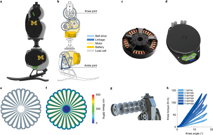
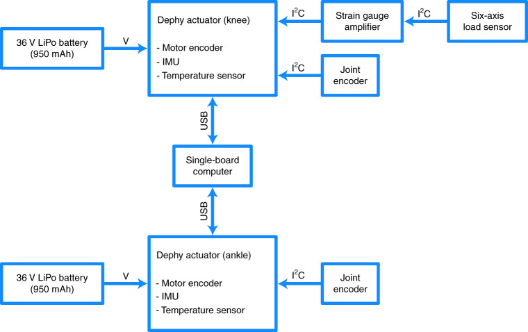
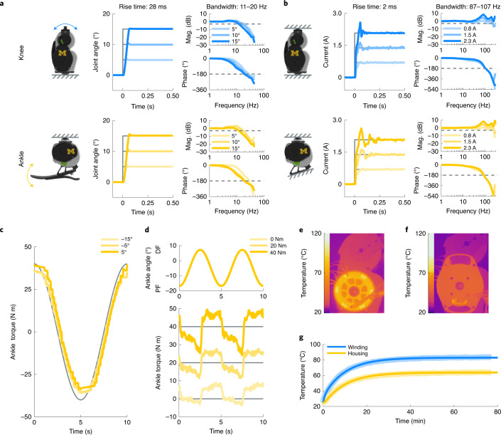
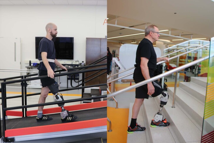
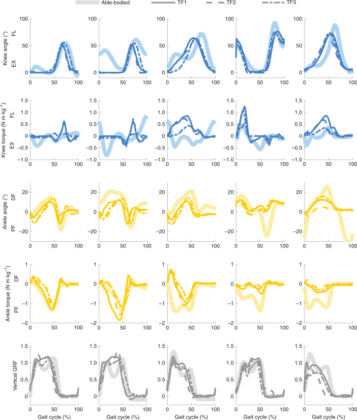
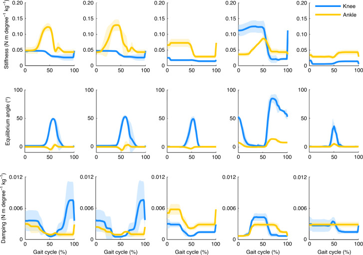
In individuals with lower-limb amputations, robotic prostheses can increase walking speed, and reduce energy use, the incidence of falls and the development of secondary complications. However, safe and reliable prosthetic-limb control strategies for robust ambulation in real-world settings remain out of reach, partly because control strategies have been tested with different robotic hardware in constrained laboratory settings. Here, we report the design and clinical implementation of an integrated robotic knee-ankle prosthesis that facilitates the real-world testing of its biomechanics and control strategies. The bionic leg is open source, it includes software for low-level control and for communication with control systems, and its hardware design is customizable, enabling reduction in its mass and cost, improvement in its ease of use and independent operation of the knee and ankle joints. We characterized the electromechanical and thermal performance of the bionic leg in benchtop testing, as well as its kinematics and kinetics in three individuals during walking on level ground, ramps and stairs. The open-source integrated-hardware solution and benchmark data that we provide should help with research and clinical testing of knee-ankle prostheses in real-world environments.


Conflict of interest statement

L.M.M. and J.-F.D. are cofounders of Dephy Inc., which supports the open-source Flexible Scalable Electronics Architecture, as well as its proprietary, commercial derivatives.

Figures

Fig. 1
Fig. 1. The OSL and its design components.
a, Rendering of the OSL. b, Schematic of the OSL, highlighting the transmission, electronics and load cell. c, Output view of the electric motor used in the OSL. d, Output view of the motor integrated with the open-source motor controller and embedded system. e, Side view of a single spring disk. f, Finite element analysis of a spring disk being deflected by the gear-shaped internal shaft. The colours represent the von Mises stress. g, Exploded view of six springs stacked inside the knee output pulley. h, Torque-angle relationship of the knee with 1–6 springs stacked inside. Each spring has a stiffness of approximately 100 N m rad−1. We tested each condition five times.
Fig. 2
Fig. 2. Recommended embedded system configuration.
High-level overview of electronics, sensors and power supplies, along with the type of communication between components. The actuators are connected in parallel with a single-board computer (Raspberry Pi) by USB; this configuration was used for the benchtop testing, with a single motor. This is the recommended configuration because it does not require knowledge of specialized communication protocols; instead, the embedded system handles the inter-integrated circuit (I2C) and USB communications for the user. LiPo, lithium polymer; V, voltage.
Fig. 3
Fig. 3. Electromechanical and thermal benchtop testing.
a, The test setup, step response and frequency response for the closed-loop position control system. The output of each joint was free to rotate for these tests. The dashed lines represent the thresholds used to calculate the bandwidth. We tested each condition five times. Mag., magnitude. b, The test setup, step response and frequency response for the closed-loop current control system. The output of each joint was locked in place for these tests. We tested each condition five times. c, Open-loop torque tracking of a sinusoidal torque trajectory while the ankle prosthesis was mechanically grounded. We tested each condition three times. d, Open-loop torque tracking of a constant torque trajectory while the ankle prosthesis was sinusoidally rotated through its range of motion. We tested each condition three times. e, Representative thermal image of the knee prosthesis, without the embedded system mounting plate, after providing the motor with a constant current of 8 A for 70 min. The windings reach a steady-state temperature of 92 °C. f, Representative thermal image of the knee prosthesis, with the mounting plate, after providing the motor with a constant current of 8 A for 70 min. The windings reach a steady-state temperature of 83 °C. g, Simulated (bold) and experimental (shaded) thermal response of the motor to a constant current of 8 A. We tested each condition twice. Series elasticity was not included in these tests.
Fig. 4
Fig. 4. Participants with a transfemoral amputation ambulating with the OSL.
Representative images of two participants ascending ramps and stairs throughout the hospital.
Fig. 5
Fig. 5. OSL kinematics and kinetics across five ambulation modes.
Mean participant (TF) and able-bodied joint angles, moments and vertical GRFs. From left to right, walking, ramp ascent, ramp descent, stair ascent, stair descent. Joint torques are normalized by participant mass and GRF is denoted as a fraction of the participant weight. Knee flexion (FL) and extension (EX) as well as ankle DF and PF directions are included for clarity. Participants walked through the circuit 15–20 times (including training and tuning trials), resulting in approximately 380 analysed steps per participant for the walking condition and 38 analysed steps per participant for the ramp and stair conditions.
Fig. 6
Fig. 6. Tuned impedance parameters across five ambulation modes.
Mean (bold) ± s.d. (shaded) of tuned stiffness, equilibrium angle and damping coefficient profiles for three participants. From left to right, walking, ramp ascent, ramp descent, stair ascent, stair descent.

References

    1. Ziegler-Graham K, MacKenzie EJ, Ephraim PL, Travison TG, Brookmeyer R. Estimating the prevalence of limb loss in the United States: 2005 to 2050. Arch. Phys. Med. Rehabil. 2008;89:422–429. - PubMed
    1. Sinha R, Van Den Heuvel WJA, Arokiasamy P. Factors affecting quality of life in lower limb amputees. Prosthet. Orthot. Int. 2011;35:90–96. - PubMed
    1. Waters RL, Perry J, Antonelli D, Hislop H. Energy cost of walking of amputees: the influence of level of amputation. J. Bone Joint Surg. Am. 1976;58:42–46. - PubMed
    1. Au SK, Herr HM. Powered ankle-foot prosthesis. IEEE Robot. Autom. Mag. 2008;15:52–59.
    1. Miller WC, Speechley M, Deathe B. The prevalence and risk factors of falling and fear of falling among lower extremity amputees. Arch. Phys. Med. Rehabil. 2001;82:1031–1037. - PubMed

Publication types