Review
. 2021 May;33(19):e2002640.
doi: 10.1002/adma.202002640. Epub 2020 Oct 6.

Functional Fibers and Fabrics for Soft Robotics, Wearables, and Human-Robot Interface

Affiliations
Review

Functional Fibers and Fabrics for Soft Robotics, Wearables, and Human-Robot Interface

Jiaqing Xiong et al. Adv Mater. 2021 May.

Abstract

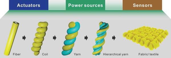
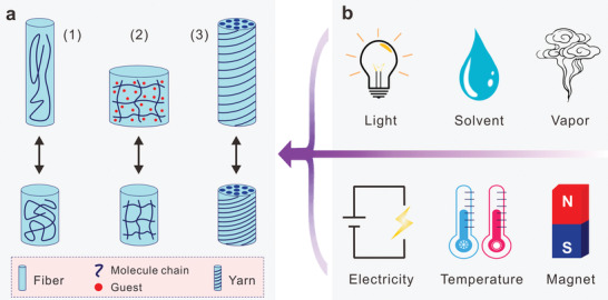
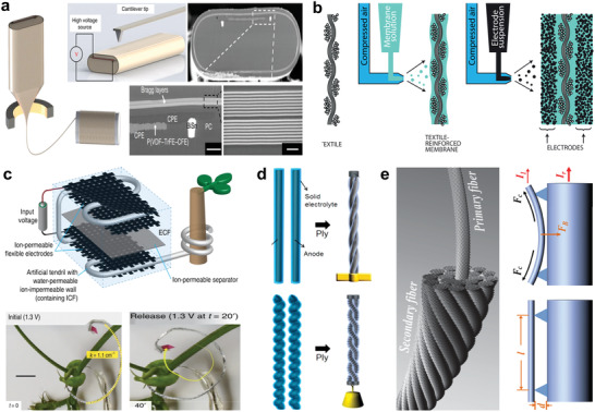
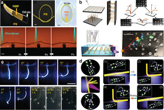
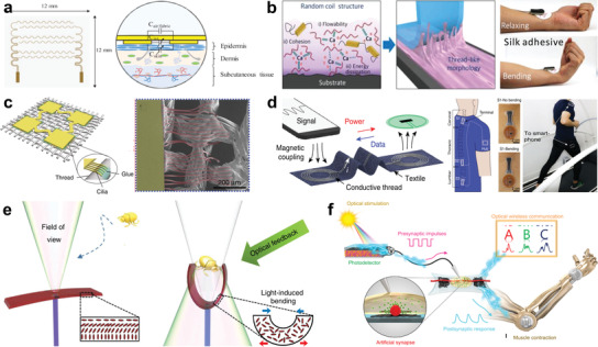
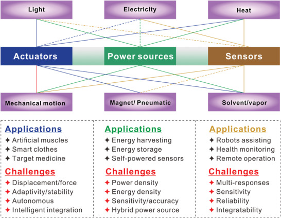
Soft robotics inspired by the movement of living organisms, with excellent adaptability and accuracy for accomplishing tasks, are highly desirable for efficient operations and safe interactions with human. With the emerging wearable electronics, higher tactility and skin affinity are pursued for safe and user-friendly human-robot interactions. Fabrics interlocked by fibers perform traditional static functions such as warming, protection, and fashion. Recently, dynamic fibers and fabrics are favorable to deliver active stimulus responses such as sensing and actuating abilities for soft-robots and wearables. First, the responsive mechanisms of fiber/fabric actuators and their performances under various external stimuli are reviewed. Fiber/yarn-based artificial muscles for soft-robots manipulation and assistance in human motion are discussed, as well as smart clothes for improving human perception. Second, the geometric designs, fabrications, mechanisms, and functions of fibers/fabrics for sensing and energy harvesting from the human body and environments are summarized. Effective integration between the electronic components with garments, human skin, and living organisms is illustrated, presenting multifunctional platforms with self-powered potential for human-robot interactions and biomedicine. Lastly, the relationships between robotic/wearable fibers/fabrics and the external stimuli, together with the challenges and possible routes for revolutionizing the robotic fibers/fabrics and wearables in this new era are proposed.

Keywords: actuators; fibers/fabrics; power sources; sensors; soft robotics.


Conflict of interest statement

The authors declare no conflict of interest.

Figures

Figure 1
Figure 1
The available forms of fibers in 1D, 3D, and 2D configurations include yarns and fabric/textile for application in actuators, sensors, and power sources.
Figure 2
Figure 2
The actuation mechanisms and different stimuli for fiber/yarn actuators. a) Three kinds of reversible deformation principles. 1) Order change, 2) volume change, and 3) distance change. b) The actuation stimuli. The purple arrow indicates the infliction of stimuli on the fiber/yarn actuators.
Figure 3
Figure 3
Electric actuated fibers/yarns. a) The thermally drawn fiber with piezoelectric PVDF. Reproduced under the terms of the CC‐BY Creative Commons Attribution 4.0 International License (http://creativecommons.org/licenses/by/4.0/).[ 68 ] Copyright 2017, The Authors, published by Springer Nature. b) An ionic and capacitive laminate actuator. Reproduced with permission.[ 73 ] Copyright 2017, Elsevier. c) A tendril like osmosis actuator that reversibly changed stiffness and performed hooking/anchoring. Reproduced under the terms of the CC‐BY Creative Commons Attribution 4.0 International License (http://creativecommons.org/licenses/by/4.0).[ 79 ] Copyright 2019, The Authors, published by Springer Nature. d) All‐solid‐state actuator consisting of twisted CNTs fiber that infiltrated with solid electrolyte. Reproduced with permission.[ 80 ] Copyright 201, American Chemical Society. e) Current‐actuated hierarchal CNTs fiber. Reproduced with permission.[ 81 ] Copyright 2014, Wiley‐VCH.
Figure 4
Figure 4
Light‐responsive fibers/yarns. a) LC coated hollow fiber for liquid manipulating by light induced capillary force change. Reproduced with permission.[ 85 ] Copyright 2019, Wiley‐VCH. b) LC fibers array controlled by space resolution light, working collectively to display patterns and transport objects. Reproduced with permission.[ 87 ] Copyright 2016, The Authors, published by Wiley‐VCH. c) Fiber actuator fabricated by hierarchical self‐assembly of supramolecular motors. Reproduced with permission.[ 91 ] Copyright 2008, Springer Nature. d) Photodeformable fiber for actuation and information encryption. Reproduced with permission.[ 92 ] Copyright 2019, Royal Society of Chemistry.
Figure 5
Figure 5
Thermally actuated fibers/yarns. a) Biodegradable SMP for minimally invasive surgical as smart suture. Reproduced with permission.[ 97 ] Copyright 2002, The American Association for the Advancement of Science (AAAS). b) Twisted SMP fiber actuator with high strain and stress and application in propeller engine. Reproduced with permission.[ 98 ] Copyright 2019, The Authors, published by The American Association for the Advancement of Science (AAAS). c) Janus structured actuator made of two ordinary materials with different thermal properties. A tripod walking robot was demonstrated. Reproduced with permission.[ 101 ] Copyright 2016, American Chemical Society. d) Twisted and coiled polymer fiber actuator from fishing line and sewing thread. Reproduced with permission.[ 105 ] Copyright 2014, The American Association for the Advancement of Science (AAAS). e) Twisted CNTs yarn infiltrated with viscous guest, showing fast and accurate controlling. Reproduced with permission.[ 109 ] Copyright 2014, Springer Nature.
Figure 6
Figure 6
Solvent and vapor actuated fibers/yarns. a) Hierarchically arranged helical CNTs fiber actuators driven by solvents and vapors. Reproduced with permission.[ 113 ] Copyright 2014, Springer Nature. b) Sheath‐run artificial muscle composed of PEO–SO3 guest and a CNTs yarn host. Reproduced with permission.[ 115 ] Copyright 2019, The Authors, published by The American Association for the Advancement of Science (AAAS). c) Laser patterned GO–G fiber actuator and robot. Reproduced with permission.[ 118 ] Copyright 2013, Wiley‐VCH. d) Aligned nanofibers based self‐locomotive hygrobot. Reproduced with permission.[ 121 ] Copyright 2019, The Authors, published by The American Association for the Advancement of Science (AAAS). e) A smart flytrap automatic respond to multiple solvents with embodied logic. Reproduced under the terms of the CC‐BY Creative Commons Attribution 4.0 International License (https://creativecommons.org/licenses/by/4.0/).[ 122 ] Copyright 2019, The Authors, published by Springer Nature.
Figure 7
Figure 7
Magnetic and pneumatic actuators. a) 3D printed fiber actuator with patterned magnetic polarity. Reproduced with permission.[ 132 ] Copyright 2018, Springer Nature. b) 3D printed programmable pneumatic actuator. Reproduced under the terms of the CC‐BY Creative Commons Attribution 4.0 International License (https://creativecommons.org/licenses/by/4.0/).[ 134 ] Copyright 2018, The Authors, published by Springer Nature. c) 3D printed reprogrammable pneumatic actuator. Reproduced under the terms of the CC‐BY Creative Commons Attribution 4.0 International License (https://creativecommons.org/licenses/by/4.0/).[ 135 ] Copyright 2019, The Authors, published by Springer Nature.
Figure 8
Figure 8
Fiber actuator for soft gripper. a) A tendril like pneumatic gripper catching a fish egg and an ant. Reproduced under the terms of the CC‐BY Creative Commons Attribution 4.0 International License (https://creativecommons.org/licenses/by/4.0/).[ 142 ] Copyright 2015, Springer Nature. b) A variety of grippers constructed from the 3D printed tendril like actuators. Reproduced with permission.[ 143 ] Copyright 2018, American Chemical Society. c) Hinge‐like gripper and the outward bending gripper. Reproduced with permission.[ 144 ] Copyright 2019, Elsevier. d) A robotic arm with a telescope arm and a claw. Reproduced with permission.[ 145 ] Copyright 2016, American Chemical Society.
Figure 9
Figure 9
Fiber actuator as artificial muscle for disabled human and humanoid robots. a) A low‐working‐temperature PE fiber actuator for human finger motion assisting. Reproduced under the terms of the CC‐BY Creative Commons Attribution 4.0 International License (https://creativecommons.org/licenses/by/4.0/).[ 152 ] Copyright 2016, The Authors, published by Springer Nature. b) Soft artificial muscles made by weaving and knitting with tunable force and strain. Reproduced with permission.[ 136 ] Copyright 2017, The Authors, published by American Association for the Advancement of Science (AAAS). Reprinted/adapted from ref. [ 136 ]. © The Authors, some rights reserved; exclusive licensee American Association for the Advancement of Science. Distributed under a Creative Commons Attribution NonCommercial License 4.0 (CC BY‐NC) http://creativecommons.org/licenses/by‐nc/4.0/. c) A robot limb actuated by double helix nylon and spandex fiber to perform finger grasping and elbow bending. Reproduced with permission.[ 156 ] Copyright 2018, Wiley‐VCH. d) Electro‐thermal‐mechanical model controlled robotic hand powered by super coiled nylon fiber. Reproduced with permission.[ 157 ] Copyright 2017, IEEE.
Figure 10
Figure 10
Smart clothes for human assistance and augmentation. a) Actuating fiber based smart splint for injured finger rehabilitation. Reproduced with permission.[ 159 ] Copyright 2016. The Authors, published by Wiley‐VCH. b) The breathable and fast‐dry clothes. Reproduced with permission.[ 138 ] Copyright 2018, Royal Society of Chemistry. c) A moisture‐responsive textile for breathable quick‐dry clothes. Reproduced with permission.[ 137 ] Copyright 2019, Wiley‐VCH. d) Thermal management clothes with functions of passive heat dissipation enhancement. Reproduced with permission.[ 160 ] Copyright 2019, American Chemical Society. e) A metatextile with smart and dynamically adaptive IR optical properties. Reproduced with permission.[ 167 ] Copyright 2019, The Authors, published by The American Association for the Advancement of Science (AAAS).
Figure 11
Figure 11
Fiber‐based actuators and sensors system. a) Origami robot integrated actuator, configuration sensor and communication antenna. Reproduced with permission.[ 185 ] Copyright 2019, The Authors, published by The American Association for the Advancement of Science (AAAS). b) Master–slave fiber robot system that controlled by operator. Reproduced under the terms of the CC‐BY Creative Commons Attribution 4.0 International License (https://creativecommons.org/licenses/by/4.0/).[ 139 ] Copyright 2019, The Authors, published by MDPI. c) Silver nanowire plated bimorph tendril like fiber for humanoid limb as artificial muscle and angle sensor. Reproduced with permission.[ 186 ] Copyright 2019, The Authors, published by The American Association for the Advancement of Science (AAAS).
Figure 12
Figure 12
Fiber‐based mechanical sensors. a) A stretchable graphene‐coated PU yarn piezoresistive sensor for robots and human motions detecting. Reproduced with permission.[ 205 ] Copyright 2015, Wiley‐VCH. b) PANI/AuNW patches integrated textile glove for robot arm manipulation. Reproduced with permission.[ 206 ] Copyright 2015, American Chemical Society. c) Ag‐rich shelled PU fiber piezoresistive sensor for a hand robot control and deformation monitoring of an artificial bladder. Reproduced with permission.[ 207 ] Copyright 2018, American Chemical Society. d) Post‐coated rubber latex thread/PU fibers/P(VDF‐TrFE) nanofibers/AgNWs integrated piezoresistive strain sensor. Reproduced with permission.[ 208 ] Copyright 2016, Wiley‐VCH. e) In situ polymerizated PEDOT coated polyester fiber piezoresistive strain sensor. Reproduced with permission.[ 209 ] Copyright 2017, American Chemical Society. f) Extruded ionic liquid/silicone elastomer concentric piezoresistive strain sensor. Reproduced with permission.[ 210 ] Copyright 2015, Wiley‐VCH. g) Wet‐spun CNTs/silicone elastomer piezoresistive core–shell fiber sensor. Reproduced with permission.[ 211 ] Copyright 2018, American Chemical Society. h) Microfluidic spinning technique with multichannels. Reproduced with permission.[ 212 ] Copyright 2018, American Chemical Society. i) Thermal drawing fibers with multiple components. Reproduced with permission.[ 213 ] Copyright 2019, Wiley‐VCH.
Figure 13
Figure 13
Fabric‐based mechanical sensors. a) Carbonized silk fabric piezoresistive strain sensor. Reproduced with permission.[ 235 ] Copyright 2016, Wiley‐VCH. b) Bar‐coated graphite silk piezoresistive strain sensor. Reproduced with permission.[ 236 ] Copyright 2016, American Chemical Society. c) In situ reduced AgNPs coated polyester textile piezoresistive strain sensor. Reproduced with permission.[ 238 ] Copyright 2017, Wiley‐VCH. d) In situ grown AuNPs textile piezoresistive pressure sensor. Reproduced with permission.[ 239 ] Copyright 2020, American Chemical Society. e) Adhesive thermally bonded robust Ag‐plated textile capacitive strain sensor. Reproduced with permission.[ 240 ] Copyright 2017, Wiley‐VCH. f) Brush‐printed PEDOT:PSS patterned knitted textile capacitive touch sensor. Reproduced with permission.[ 241 ] Copyright 2016, Wiley‐VCH. g) Laster patterning and electroless deposition enabled Ni/CNT functionalized polyester/cotton fabric as piezoresistive pressure sensor. Reproduced with permission.[ 242 ] Copyright 2017, Wiley‐VCH.
Figure 14
Figure 14
Fiber/fabric‐based thermal sensors. a) Stretchable PU fiber temperature sensor winded by thread coated with in situ polymerized PPy. Reproduced with permission.[ 248 ] Copyright 2016, Wiley‐VCH. b) PPy incorporated TPU fiber thermal sensor. Reproduced with permission.[ 249 ] Copyright 2018, Wiley‐VCH. c) Wet‐spun rGO fiber temperature sensor. Reproduced with permission.[ 250 ] Copyright 2018, Wiley‐VCH. d) Upconversion nanoparticles enabled stretchable PDMS temperature‐sensitive optical fiber. Reproduced with permission.[ 251 ] Copyright 2019, Wiley‐VCH. e) Dual‐mode fabric for temperature and pressure sensors. Reproduced with permission.[ 252 ] Copyright 2019, Wiley‐VCH. f) 3D printing hybrid yarn integrated with supercapacitor and temperature sensor. Reproduced under the terms of the CC‐BY Creative Commons Attribution 4.0 International License (https://creativecommons.org/licenses/by/4.0/).[ 253 ] Copyright 2018, The Authors, published by Wiley‐VCH.
Figure 15
Figure 15
Fiber/fabric‐based humidity sensors. a) Wet‐spun nitrogen‐doped graphene fiber humidity sensor. Reproduced with permission.[ 256 ] Copyright 2018, Wiley‐VCH. b) Wet‐spun CNT/PVA fiber humidity sensor. Reproduced with permission.[ 257 ] Copyright 2018, American Chemical Society. c) Abnormal cross‐sectioned hydrophobic fibers winded humidity sensor. Reproduced with permission.[ 258 ] Copyright 2019, Wiley‐VCH. d) Thermal drawn polyetherimide fiber humidity sensor. Reproduced under the terms of the CC‐BY Creative Commons Attribution 4.0 International License (https://creativecommons.org/licenses/by/4.0/).[ 259 ] Copyright 2018, The Authors, published by MDPI. e) Nickel/GO electroless plated silk fabric humidity sensor. Reproduced with permission.[ 260 ] Copyright 2018, Royal Society of Chemistry.
Figure 16
Figure 16
Fiber/fabric‐based metabolite sensors. a) A colorimetric textile by functional depositing with indicator dye or lactate assay for sweat pH and lactate detection. Reproduced with permission.[ 265 ] Copyright 2019, Elsevier. b) A three conductive threads‐based textile for constant detection of perspiration level. Reproduced under the terms of the CC‐BY Creative Commons Attribution 4.0 International License (https://creativecommons.org/licenses/by/4.0/).[ 266 ] Copyright 2018, The Authors, published by MDPI. c) A stretchable power textile with screen‐printed hybrid supercapacitor‐biofuel cell. Reproduced with permission.[ 267 ] Copyright 2018, Royal Society of Chemistry. d) A textile biofuel cell for self‐powered source. Reproduced with permission.[ 268 ] Copyright 2014, Royal Society of Chemistry. e) A stretchable textile biofuel cell for self‐powered sweat sensor. Reproduced with permission.[ 269 ] Copyright 2016, Royal Society of Chemistry.
Figure 17
Figure 17
Thermoelectric self‐powered fibers/fabrics. a) A wearable thermoelectric glass fabric. Reproduced with permission.[ 296 ] Copyright 2014, Wiley‐VCH. b) A π‐type structured thermoelectric thread by wet spinning. Reproduced with permission.[ 298 ] Copyright 2017, Royal Society of Chemistry. c) Thermoelectric yarns twisted by electrospun PAN nanofibers sheet sputtered with Sb2Te3 (p‐type), and Bi2Te3 (n‐type). Reproduced with permission.[ 299 ] Copyright 2016, Wiley‐VCH. d) CNT films twisted yarns deposited with PEDOT:PSS and oleamine for stretchable 3D thermoelectric fabric. Reproduced under the terms of the CC‐BY Creative Commons Attribution 4.0 International License (https://creativecommons.org/licenses/by/4.0/).[ 300 ] Copyright 2020, The Authors, published by Springer Nature.
Figure 18
Figure 18
Piezo‐/triboelectric self‐powered fibers/fabrics. a) A direct‐written PVDF piezoelectric fiber. Reproduced with permission.[ 324 ] Copyright 2010, American Chemical Society. b) Carbon fiber/ZnO nanostructures fiber PENG. Reproduced with permission.[ 325 ] Copyright 2011, Wiley‐VCH. c) A PVDF‐NaNbO3 nonwoven fabric‐based PENG. Reproduced with permission.[ 326 ] Copyright 2013, Royal Society of Chemistry. d) A fully woven PENG based on BaTiO3/PVC fiber. Reproduced with permission.[ 327 ] Copyright 2015, Elsevier. e) A continuous triboelectric yarn based on PVDF/PAN nanofibers. Reproduced with permission.[ 328 ] Copyright 2020, American Chemical Society. f) A washable triboelectric all‐textile sensor for arterial pulse waves and respiratory monitoring. Reproduced with permission.[ 329 ] Copyright 2020, The Authors, published by American Association for the Advancement of Science (AAAS). Reprinted/adapted from ref. [ 329 ]. © The Authors, some rights reserved; exclusive licensee American Association for the Advancement of Science. Distributed under a Creative Commons Attribution NonCommercial License 4.0 (CC BY‐NC) http://creativecommons.org/licenses/by‐nc/4.0/. g) A skin‐actuated sandwiched all‐fabric TENG with high sensitivity for both voluntary and involuntary contacts with human skin. Reproduced under the terms of the CC‐BY Creative Commons Attribution 4.0 International License (https://creativecommons.org/licenses/by/4.0/).[ 330 ] Copyright 2018, The Authors, published by Springer Nature. h) A wearable all‐fabric TENG with capability for moisture screening and water energy harvesting. Reproduced with permission.[ 331 ] Copyright 2017, Wiley‐VCH.
Figure 19
Figure 19
Photovoltaic self‐powered fibers/fabrics. a) A textile battery covered with film solar cell. Reproduced with permission.[ 359 ] Copyright 2013, American Chemical Society. b) Wearable solar cell by stacking CNT‐textile electrode. Reproduced with permission.[ 360 ] Copyright 2014, Wiley‐VCH. c) A colorful all‐solid woven textile solar cell. Reproduced with permission.[ 361 ] Copyright 2016, Wiley‐VCH. d) A tailorable all‐solid power solar cell textile integrated with fiber supercapacitors. Reproduced with permission.[ 362 ] Copyright 2016, American Chemical Society. e) A microcable hybrid textile for simultaneous solar and mechanical energy harvesting. Reproduced with permission.[ 363 ] Copyright 2016, Springer Nature. f) A self‐powered fabric integrated with a TENG, solar cells, and supercapacitors. Reproduced with permission.[ 364 ] Copyright 2020, The Authors, published by The American Association for the Advancement of Science (AAAS). Reprinted/adapted from ref. [ 364 ]. © The Authors, some rights reserved; exclusive licensee American Association for the Advancement of Science. Distributed under a Creative Commons Attribution NonCommercial License 4.0 (CC BY‐NC) http://creativecommons.org/licenses/by‐nc/4.0/. g) A solar cell textile with stability at a working temperature range of −40 to 160 °C. Reproduced with permission.[ 366 ] Copyright 2016, Royal Society of Chemistry.
Figure 20
Figure 20
Fiber‐robots for biomedical applications in vivo. a) A magnetite remotely navigable multisegmented continuum fiber robot with controllable softness. Reproduced under the terms of the CC‐BY Creative Commons Attribution 4.0 International License (https://creativecommons.org/licenses/by/4.0/).[ 374 ] Copyright 2019, The Authors, published by Wiley‐VCH. b) Hydrogel skin enabled self‐lubricating ferromagnetic fiber‐robot. Reproduced with permission.[ 375 ] Copyright 2019, The Authors, published by The American Association for the Advancement of Science (AAAS). c) An injectable helical‐CNTs‐yarn electrochemical sensor for multiple disease biomarkers monitoring in vivo. Reproduced with permission.[ 376 ] Copyright 2019, Springer Nature.
Figure 21
Figure 21
Challenge of fibers/fabrics for wearables and soft robotics. a) A simulation method for designing a capacitive hydration sensor incorporable with textile. Reproduced with permission.[ 393 ] Copyright 2016, Cambridge University Press. b) A calcium‐modified silk fibroin strong adhesive for enhancing interfacial stability between device and skin. Reproduced with permission.[ 394 ] Copyright 2018, Wiley‐VCH. c) An artificial cilia‐assisted transfer technique to adhere devices onto textile. Reproduced under the terms of the CC‐BY Creative Commons Attribution 4.0 International License (https://creativecommons.org/licenses/by/4.0/).[ 395 ] Copyright 2016, The Authors, published by Springer Nature. d) A battery‐free NFC clothing with body sensor network for wireless power and data connectivity around the human body. Reproduced under the terms of the CC‐BY Creative Commons Attribution 4.0 International License (https://creativecommons.org/licenses/by/4.0/).[ 396 ] Copyright 2016, The Authors, published by Springer Nature. e) A self‐regulated light‐driven artificial flytrap. Reproduced under the terms of the CC‐BY Creative Commons Attribution 4.0 International License (https://creativecommons.org/licenses/by/4.0/).[ 397 ] Copyright 2017, The Authors, published by Springer Nature. f) A reflex like sensorimotor nervous synapse. Reproduced with permission.[ 398 ] Copyright 2018, The Authors, published by American Association for the Advancement of Science (AAAS). Reprinted/adapted from ref. [ 398 ]. © The Authors, some rights reserved; exclusive licensee American Association for the Advancement of Science. Distributed under a Creative Commons Attribution NonCommercial License 4.0 (CC BY‐NC) http://creativecommons.org/licenses/by‐nc/4.0/.
Figure 22
Figure 22
Relationship map of stimuli from human body or surrounding environments for fibers/fabrics application in actuators, sensors, and power sources. Blue lines indicate the actuators could be driven by the corresponding stimuli. Yellow lines mean the sensors could detect the corresponding stimuli. Green lines indicate fibers/fabrics generators could harvest energy from the related stimuli. The dashed lines suggest the relationships that are yet not been well built based on fibers/fabrics.

References

    1. Gries T., Raina M., Quadflieg T., Stolyarov O., Textile Fibre Composites in Civil Engineering, Elsevier, Amsterdam, The Netherlands: 2016, p. 3.
    1. Vigo T. L., Textile Processing and Properties: Preparation, Dyeing, Finishing and Performance, Vol. 11, Elsevier, Amsterdam, The Netherlands: 2013.
    1. Zeng W., Shu L., Li Q., Chen S., Wang F., Tao X. M., Adv. Mater. 2014, 26, 5310. - PubMed
    1. Weng W., Chen P., He S., Sun X., Peng H., Angew. Chem., Int. Ed. 2016, 55, 6140. - PubMed
    1. Jost K., Dion G., Gogotsi Y., J. Mater. Chem. A 2014, 2, 10776.

LinkOut - more resources