. 2020 Aug;5(8):1901044.
doi: 10.1002/admt.201901044. Epub 2020 May 26.

Extrusion and Microfluidic-based Bioprinting to Fabricate Biomimetic Tissues and Organs

Affiliations

Extrusion and Microfluidic-based Bioprinting to Fabricate Biomimetic Tissues and Organs

Elham Davoodi et al. Adv Mater Technol. 2020 Aug.

Abstract

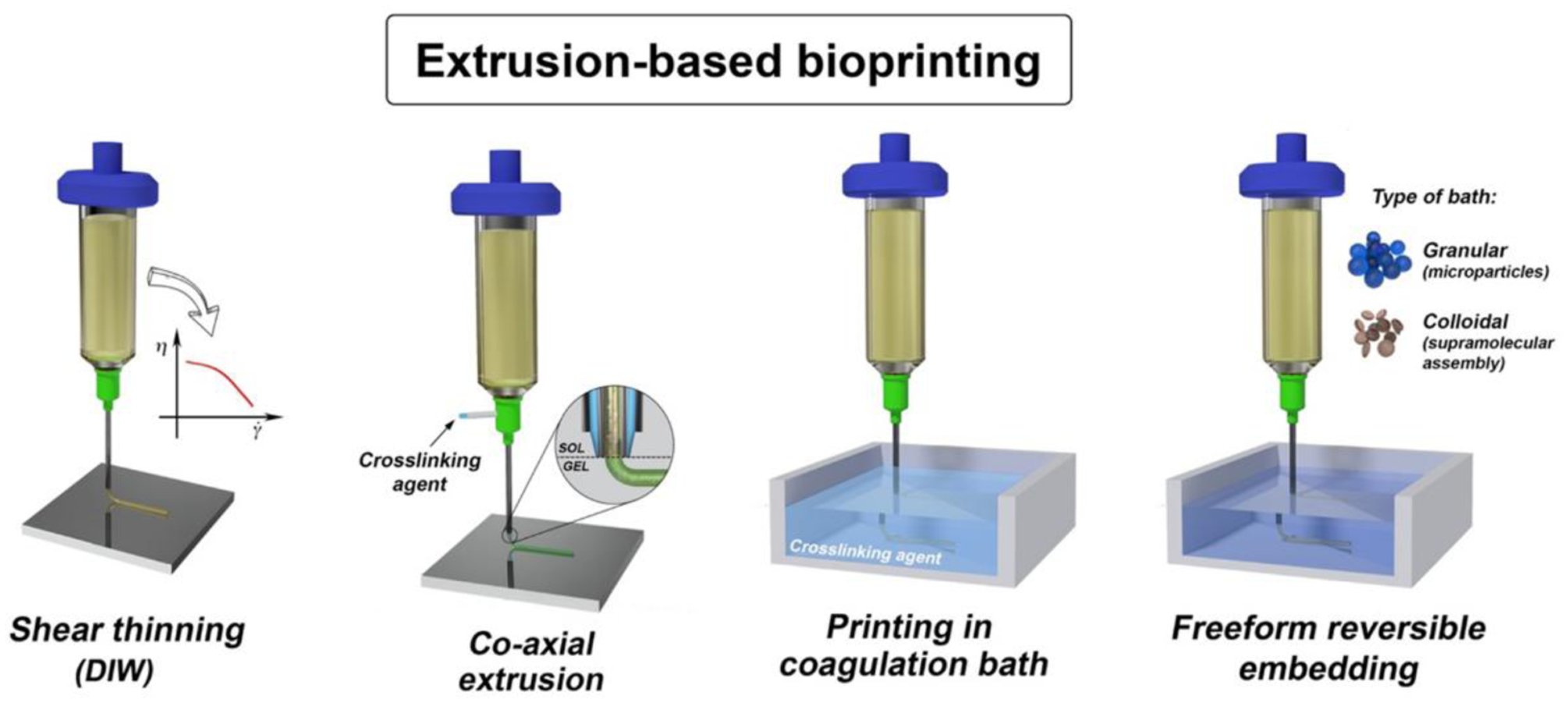
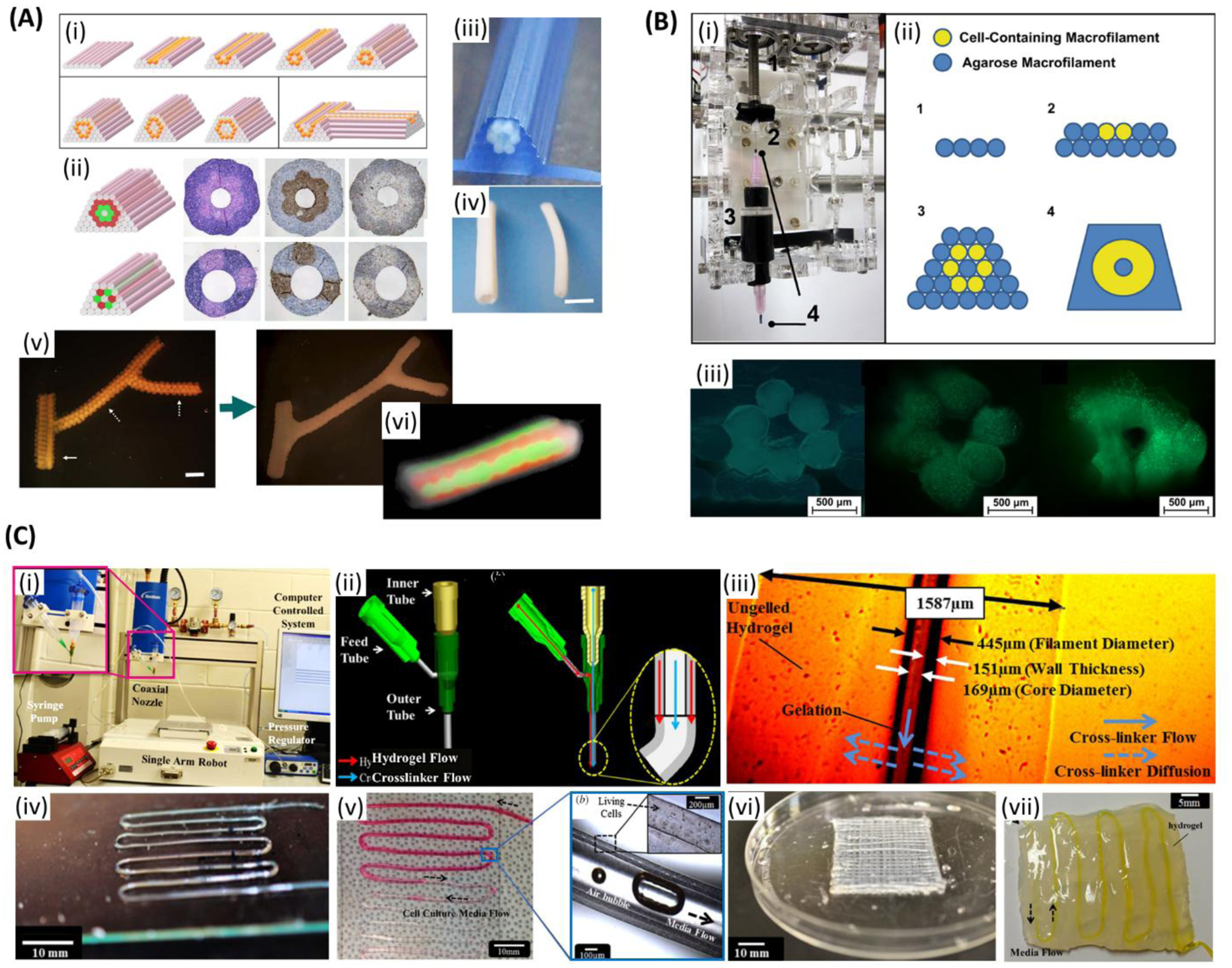
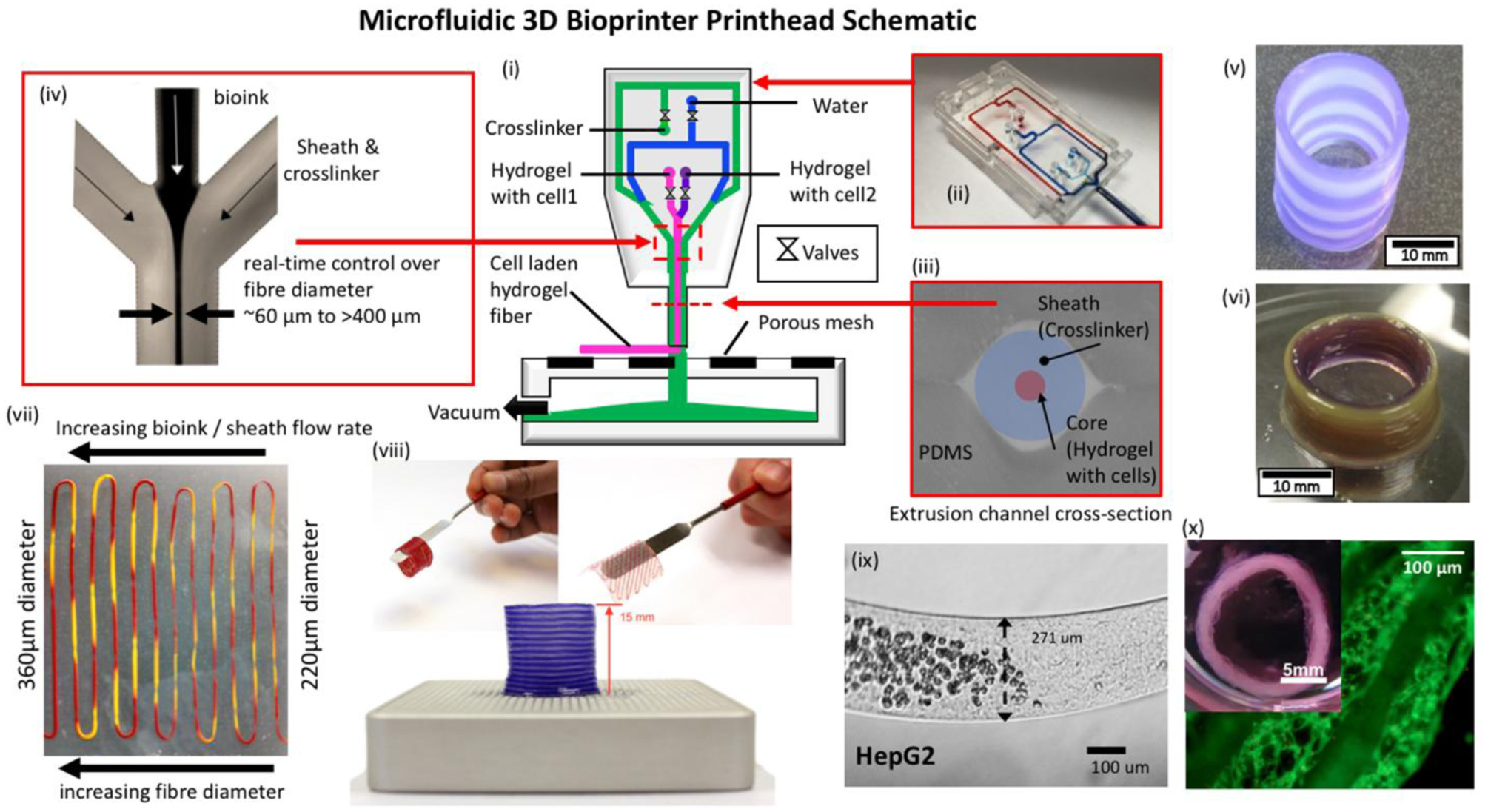
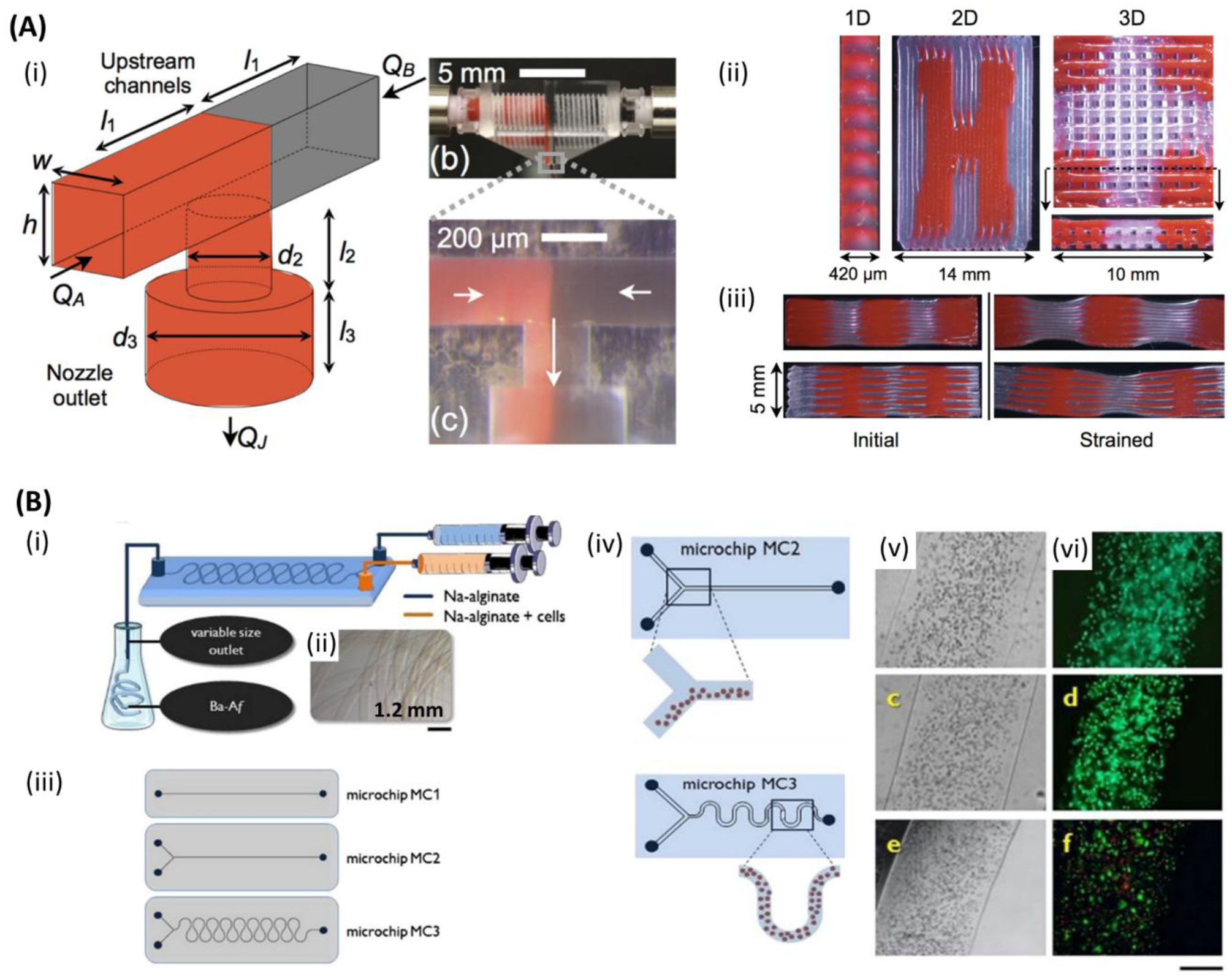
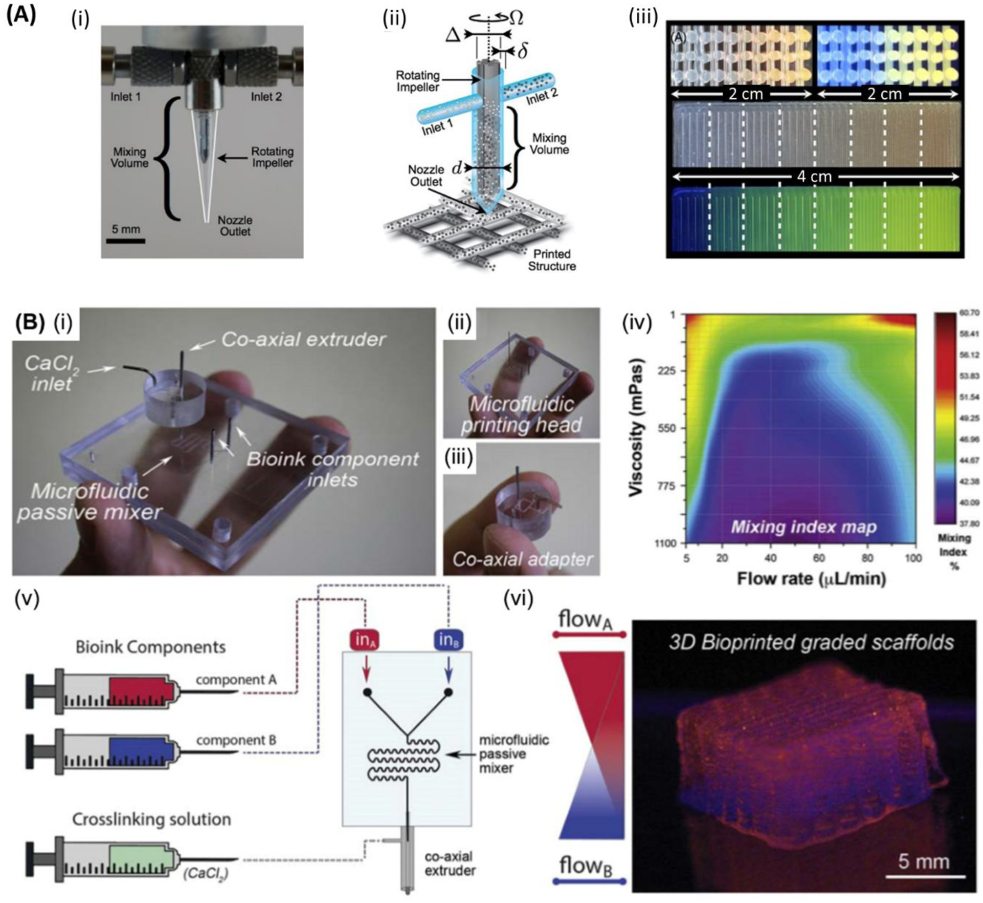
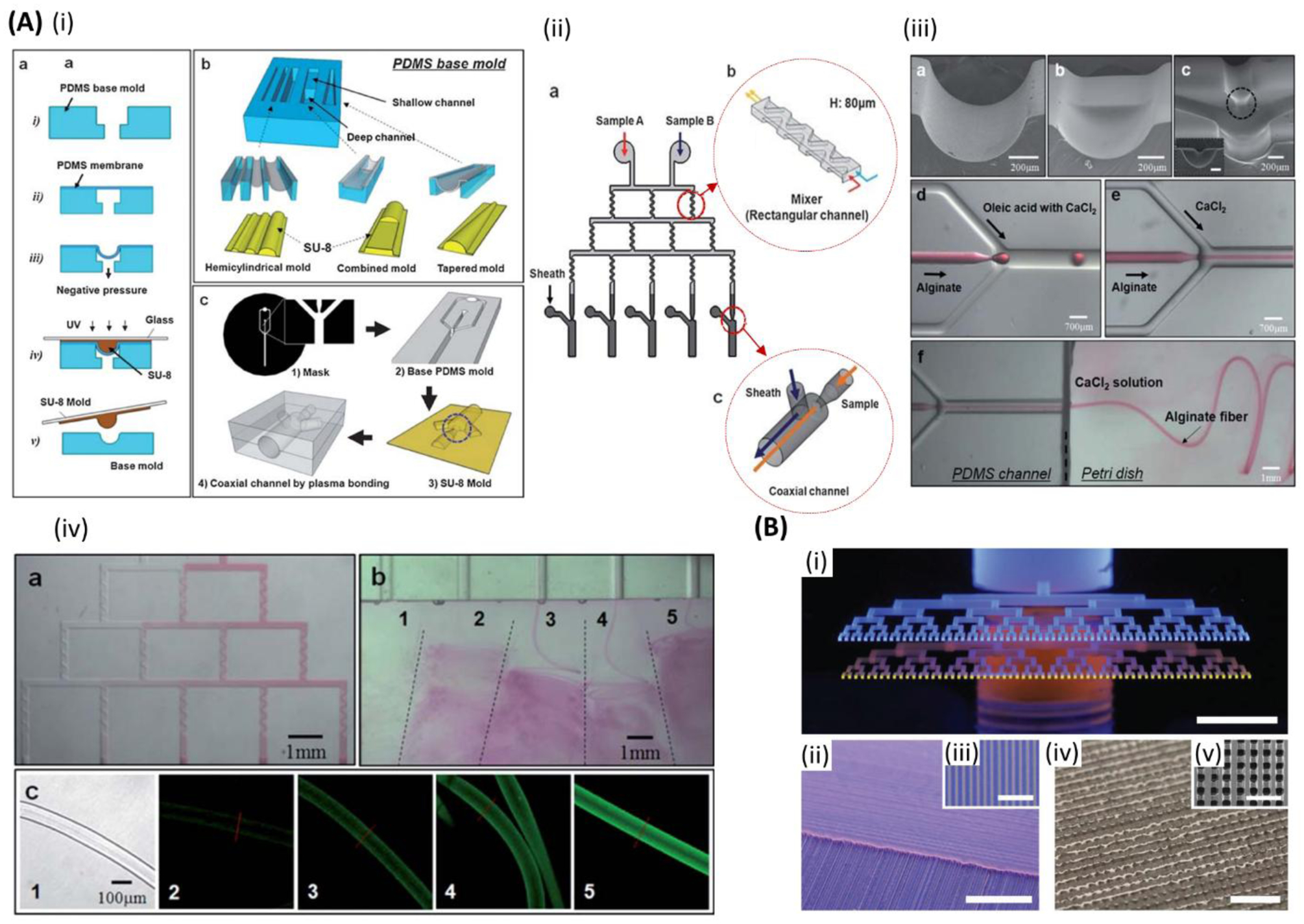
Next generation engineered tissue constructs with complex and ordered architectures aim to better mimic the native tissue structures, largely due to advances in three-dimensional (3D) bioprinting techniques. Extrusion bioprinting has drawn tremendous attention due to its widespread availability, cost-effectiveness, simplicity, and its facile and rapid processing. However, poor printing resolution and low speed have limited its fidelity and clinical implementation. To circumvent the downsides associated with extrusion printing, microfluidic technologies are increasingly being implemented in 3D bioprinting for engineering living constructs. These technologies enable biofabrication of heterogeneous biomimetic structures made of different types of cells, biomaterials, and biomolecules. Microfluiding bioprinting technology enables highly controlled fabrication of 3D constructs in high resolutions and it has been shown to be useful for building tubular structures and vascularized constructs, which may promote the survival and integration of implanted engineered tissues. Although this field is currently in its early development and the number of bioprinted implants is limited, it is envisioned that it will have a major impact on the production of customized clinical-grade tissue constructs. Further studies are, however, needed to fully demonstrate the effectiveness of the technology in the lab and its translation to the clinic.

Keywords: Bioprinting; bioink; biomimetic; microfluidics; tissue engineering.


Figures

Figure 1.
Figure 1.
Illustration of the most popular extrusion three-dimensional bioprinting strategies. Reproduced with permission.[92] Copyright 2018, IOP Publishing.
Figure 2.
Figure 2.
Extrusion bioprinting of vascularized tissue. A) (i) Complex three-dimensional tubular structures formation through layer-by-layer deposition of agarose rods (pink) and multicellular spheroids (orange). (ii) Tubular structures based on two different patterns with multicellular double-layer wall (green: human umbilical vein smooth muscle cells (HUVSMCs); red: human skin fibroblasts (HSFs)) before and after 3 days of fusion. (iii) Printed tubular construct. (iv) Bioprinted pig smooth muscle cells (SMCs) tubes with different diameters after 3 days of fusion. Outer diameters are 2.5 mm (left), and 1.5 mm (right). (v) Printed branched structure just after printing (left) and the final fused structure after 6 days (right). Spheroids are 300 μm and branches pointed with solid and broken arrows are 1.2 mm and 0.9 mm, respectively. (vi) Fluorescent image of the tubular structure showing the fusion pattern after 7 days of printing. Scale bars: (iv) 2.5mm, (v) 1.2 mm. Reproduced with permission.[129] Copyright 2009, Elsevier. B) (i) A customized adaptor for microcapillary-based printing. (ii) Developing a tubular structure through layer-by-layer printing of cell- encapsulated hydrogel microfilaments. (iii) Fluorescent images of the cross-section of cell-laden tubular constructs just after printing, after 14 days, and 28 days of culture, respectively. (green: live cells; red: dead cells). Scale bars: 500 μm. Reproduced with permission.[130] Copyright 2010, Elsevier. C) (i) Single-arm robotic printer with co-axial nozzle. (ii) Schematic of the co-axial nozzle with hydrogel and the crosslinker flow. (iii) The influence of the hydrogel properties in the dimensions of the hollow filaments. (iv) A single-layer microfluidic channel network. (v) Media flow through bovine cartilage progenitor cell-laden alginate microchannel. (vi) An eight-layer microfluidic channel network. (vii) Microfluidic channel embedded in bulk hydrogel. Scale bars: (iv) 10 mm, (v) 10 mm, magnified image: 100 μm, (vi) 10 mm, (vii) 5 mm. Reproduced with permission.[131] Copyright 2013, IOP Publishing.
Figure 3.
Figure 3.
Microfluidic bioprinting principles. (i) Schematic of a microfluidic 3D bioprinting system depicting a (ii) two material PDMS microfluidic printhead with integrated pneumatic valves and (iii)&(iv) co-axial flow focusing extruder capable of generating hydrogel fibers with diameters ~60μm - >400μm. Integration with a 3-axis positioning system and custom software enables a variety of multimaterial structures to be fabricated including.[79] Copyright 2013, IEEE. (v) Tubular structures with inter-layer switching and (vi) concentric tubular structures with in-plane intra-layer material switching. Flow control over the ratio of hydrogel and crosslinker flow rate enables (vii) sequenced 2-material fibers with on-the-fly control over fiber diameter. (viii) Printed alginate structures are robust and can be manual manipulated directly post-printing. (ix) Abrupt switching between regions containing cells and those without cells is possible. A variety of different cells have been validated in the hydrogel fiber platform including (x) human airway primary smooth muscle cells in an alginate collagen fiber and cultured to produce a functional airway contraction model.
Figure 4.
Figure 4.
Microfluidic bioprinting chips. A) (i) Schematic of a microfluidic printhead for multimaterial printing with controlled flow rate of each material by independently actuated syringe pumps. (ii) One-, two-, and three-dimensional (1D, 2D, and 3D) printed multimaterial PDMS (red and clear) structures. (iii) Cross-section images of two different multimaterial 3D structures with different stiffness. Initial form of the structures (left), and after applying strain (right). Reproduced with permission.[184] Copyright 2015, WILEY-VCH Verlag GmbH & Co. B) (i) Schematic of the microfluidic chip for alginate microfibers formation. (ii) Micrograph image of the alginate microfiber formed by microfluidic chip. (iii) One and two inlets straight channel microfluidic chips (top and middle) and two inlets snake-shape channel micromixing chip (bottom) for cell-laden alginate microfibers formation. (iv) Schematic of segregated vs homogenous cell distribution within alginate microfibers when employing straight channel and snake-shape channel microchips. (v) Optical and (vi) fluorescent images of sarcoma osteogenic (SaOS-2) osteoblast-like cells laden in alginate microfibers after 1 day (top (both)), 7 days (middle (both)), and 14 days (bottom (both)). (green: live; red: dead). Scale bar: 250 μm. Reproduced with permission.[181] Copyright 2015, Elsevier.
Figure 5.
Figure 5.
Microfluidic bioprinting of cell-encapsulated microspheres. A) (i) Schematic of bone marrow derived mesenchymal stem cells (BMSCs)-encapsulated gelatin methacryloyl (GelMA) microsphere generation for bone regeneration. (ii) Microfluidic device. (iii) GelMA droplets formation. (iv) Monodisperse GelMA microdroplets. (v) Crosslinked GelMA microspheres. (vi) Implanting the microspheres into the rabbit femoral defect. (vii) New bone volume (%) when implanting normal saline (control) and various contents of microspheres. Reproduced with permission.[299] Copyright 2016, WILEY-VCH Verlag GmbH & Co. B) Selectively gelation of microniches: (i) The process starts with injecting hydrochloric acid and ethylenediaminetetraacetic acid (HCL/EDTA) matrix precursors, diluted solution of CaCo3-loaded cells and inactivated FXII into microfluidic chip, followed by jointing the solution in a laminar flow and shearing the fluid stream with the oily phase, resulting in monodispersed droplets. In the droplets containing CaCo3-loaded cells, HCL dissolve CaCo3 and realise Ca2+ ions that activate FXIII and results in on-demand gelation. (ii) Droplets in the collection channel. (iii) Fluorescent image of the cells (blue: nuclei). Reproduced with permission.[194] Copyright 2017, Royal Society of Chemistry. C) (i) 3D multifunctional biostructures fabrication: Single-cell laden microgel formation followed by modular bioink preparation, and finally 3D bioprinting of multifunctional biomaterials with uncoupled micro- and macroenvironments. (ii) Single cell encapsulation in polyethylene glycol diacrylate (PEGDA) precursor (iii,iv) Schematic and SEM images of failed and prosperous encapsulation using single and dual photoinitiator system, respectively. (v) Cell encapsulation quality regarding the relative position of the encapsulated cells within microgel. (vi) Live/dead staining of encapsulated cells. (green: live; red: dead) (vii) Flow cytometry-based sorting of the cell-laden microgels. Scale bars: (ii-iv, vi,vii) 50 μm. Reproduced with permission.[186] Copyright 2017, WILEY-VCH Verlag GmbH & Co.
Figure 6.
Figure 6.
Microfluidic bioprinting of vascularized tissue. A) (i) Steps followed for microfluidic bioprinting of multilayered tubular hydrogel constructs. (ii) Images of bioprinted tubular constructs. (iii) Fabrication of tunable single and double layered tubes. (iv) Fluorescence images representing dynamic variation between single and double layered tube. (v) Live/dead assay of human umbilical vein endothelial cells (HUVECs) and human smooth muscle cells (hSMCs) encapsulated within the tubes on day 14. Scale bars: (ii, iv) 1cm, (v) 500 μm. Reproduced with permission.[85] Copyright 2018, WILEY-VCH Verlag GmbH & Co. B) Co-axial microfluidic nozzle for hollow Ca-alginate filaments formation. (ii-v)) Continues gel layer with embedded single and dual layer channels. (ii) Single and dual layer patterns. (iii) Cross-section of the continues gel with embedded hollow channels. (iv) Printed parallel straight channels (left), their arc connections (middle), and dual layer channels (right). (v) Fluorescent images illustrating the nanoparticles flow along the channels shown in (iv), respectively. Scale bars: 1 mm. Reproduced with permission.[187] Copyright 2016, SPIE.
Figure 7.
Figure 7.
Microfluidic bioprinting of organoids. (i) A microfluidic device for generation of sandwich-structured alginate microfiber with hepatocytes and 3T3 cells layers. (ii) Formation process of scaffold-free hepatocyte-3T3 complex microorganoid. (iii) Hepatocytes and 3T3 cells-encapsulated hydrogel microfibers formation by microfluidic device. (iv) Micrographs of hepatocytes in microfibers with and without presence of 3T3 cells. (v) Double-immunofluorescent staining of hepatocytes-encapsulated microfibers with and without 3T3 using CK18 (green) and vimentin (red) antibodies. (green: hepatocytes; red: 3T3). (vi) Production of hepatic microorganoids in alginate microfibers: without 3T3 after (a) 7 and (e) 30 days, and with 3T3 after (b) 7 and (f) 30 days. Enzymatic digest of the alginate microfibers and hepatic microorganoids recovery for the microfibers: without 3T3 after (c) 7 and (g) 30 days, and with 3T3 after (d) 7 and (h) 30 days. Scale bars: (iii) 200 μm, (iv) 100 μm, (v) 50 μm, (vi) 200 μm. Reproduced with permission.[188] Copyright 2012, Elsevier.
Figure 8.
Figure 8.
Multimaterial bioprinting. A) (i) Fabrication process of three-dimensional (3D) cell-laden constructs: (a) Layer-by-layer bioprinting of 3D constructs along with two steps of crosslinking. (b,c) Bioink consisting of gelatin methacryloyl (GelMA), alginate, photoinitiator and cells are extruded through inner nozzle, while CaCl2 flows through outer nozzle resulting in ionically crosslinking of alginate followed by ultraviolet (UV) light crosslinking of GelMA. (ii) Final 3D construct and μCT reconstructions. (iii) Multimaterial bioprinting using a microfluidic chip for developing constructs made of two separate bioinks: (b,c) alternatively (d,e) alternate and simultaneously, and (f–i) simultaneously extrusion. Red and green colors in the fluorescent images present two separate bioink extruded through Y-shape channel of a co-axial needle. (iv) (a) Schematic of the bioprinted microfibers before and after the migration of the encapsulated human umbilical vein endothelial cells (HUVECs) to the outer regions of the microfibers after 10 days of culture. Confocal microscopy images of the tubular microfibers: (b) top, and (c) cross-sectional view. Scale bars: (iii: c,e,g) 500 μm, (iii: h)200 μm, (iii: i) 50 μm, (iv) 100 μm. Reproduced with permission.[111] Copyright 2016, WILEY-VCH Verlag GmbH & Co. B) (i) The fabrication procedure of a microfluidic printhead ;(ii) Schematic of the microfluidic printhead integrated with a customized bioprinter for multimaterial/multicellular bioprinting of cell-encapsulated scaffolds followed by UV light curing. Reproduced with permission.[112] Copyright 2017, Springer.
Figure 9.
Figure 9.
Graded structure bioprinting. A) (i) Optical image of an impeller-based mixer. (ii) Schematic of a mixing nozzle for active homogenization of two inks entered through inlets #1 and #2 for three-dimensional (3D) printing of constructs of multiple materials. (iii) Cross-section images of 3D lattice constructs showing the continuous variation of the fluorescent pigment concentration under bright light (top left) and UV light (top right). 2D structures showing the discrete variation of fluorescent under 8 different mixing ratios under bright light (middle), and UV light (bottom), respectively. Scale bars: (i) 5mm. Reproduced with permission.[192] Copyright 2015, American Physical Society. B) (i) Microfluidic extrusion system composed of (ii) the microfluidic printing head and (iii) the co-axial adapter. (iv) Mixing index heatmap is shown. In (v) and (vi) the schematic of the fabrication process and the final 3D bioprinted graded scaffold are shown, respectively. Reproduced with permission. [172] Copyright 2019, IOP Publishing.
Figure 10.
Figure 10.
High-throughput microfluidic bioprinting. A) (i) Schematic of the fabrication process of the co-axial microfluidic chips. (ii) Schematic of the platform for (a) high-throughput printing of fibers with various compositions employing several (b,c) micromixers and co-axial flow channels with separate inlets for sheath flow. (iii) SEM images of (a-c) hemicylindrical, rectangular and cylindrical combination, and hemi-co-axial-flow channels, respectively. (d,e) Microdroplets and continues flow formation through the co-axial-flow channels, respectively. (f) Alginate microfiber formation through co-axial-flow channel. (iv) (a) Generation of a stepwise gradient in the fluid passing the channels with in-line micromixers, (b) high-throughput production of microfibers, and (c) optical and fluorescence images of fluorescein isothiocyanate tagged to bovine serum albumin (FITC-BSA)-immobilized fibers fabricated through various channels. Scale bars: (iii:a,b,c) 200 μm, (iii:d,e) 700 μm, (iii:f) 1 mm, (iv:a,b) 1mm, (iv:c) 100 μm. Reproduced with permission.[189] Copyright 2010, Royal Society of Chemistry. B) High-throughput multimaterial printing through dual hierarchical microvascular multinozzle printhead: (i) optical image of the printheads filled with blue (inlet above) and yellow (inlet below) inks. (ii,iii) Optical images of multilayer construct of blue and yellow wax filaments. The magnified image represents a single layer construct. (iv,v) Optical images of the printed construct out of wax filaments infilled with a photocurable epoxy resin. The magnified image shows the cross-section of a 10-layer three-dimensional (3D) construct after removing the sacrificial wax. Scale bars: (i,ii) 5 mm, (iii,iv) 2 mm, (v) 1 mm. Reproduced with permission[234]. Copyright 2013, WILEY-VCH Verlag GmbH & Co.

References

    1. Rasperini G, Acunzo R, Pellegrini G, Pagni G, Tonetti M, Pini Prato GP, Cortellini P, J. Clin. Periodontol 2018, 45, 1107. - PubMed
    1. Tonetti MS et al. , J. Clin. Periodontol 2018, 45, 78. - PMC - PubMed
    1. Jank BJ, Xiong L, Moser PT, Guyette JP, Ren X, Cetrulo CL, Leonard DA, Fernandez L, Fagan SP, Ott HC, Biomaterials 2015, 61, 246. - PMC - PubMed
    1. Takeo M, Tsuji T, Curr. Opin. Genet. Dev 2018, 52, 42. - PubMed
    1. Sanchez P, Cryobiology 2015, 71, 177.

LinkOut - more resources