. 2020 Oct 18;8(10):427.
doi: 10.3390/biomedicines8100427.

A Facile Approach for Rapid Prototyping of Microneedle Molds, Microwells and Micro-Through-Holes in Various Substrate Materials Using CO2 Laser Drilling

Affiliations

A Facile Approach for Rapid Prototyping of Microneedle Molds, Microwells and Micro-Through-Holes in Various Substrate Materials Using CO2 Laser Drilling

Yu-Wei Chen et al. Biomedicines. .

Abstract

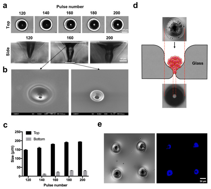
CO2 laser manufacturing has served as an enabling and reliable tool for rapid and cost-effective microfabrication over the past few decades. While a wide range of industrial and biological applications have been studied, the choice of materials fabricated across various laser parameters and systems is often confounded by their complex combinations. We herein presented a unified procedure performed using percussion CO2 laser drilling with a range of laser parameters, substrate materials and various generated microstructures, enabling a variety of downstream tissue/cellular-based applications. Emphasis is placed on delineating the laser drilling effect on different biocompatible materials and proof-of-concept utilities. First, a polydimethylsiloxane (PDMS) microneedle (MN) array mold is fabricated to generate dissolvable polyvinylpyrrolidone/polyvinyl alcohol (PVP/PVA) MNs for transdermal drug delivery. Second, polystyrene (PS) microwells are optimized in a compact array for the formation of size-controlled multicellular tumor spheroids (MCTSs). Third, coverglass is perforated to form a microaperture that can be used to trap/position cells/spheroids. Fourth, the creation of through-holes in PS is validated as an accessible method to create channels that facilitate medium exchange in hanging drop arrays and as a conducive tool for the growth and drug screenings of MCTSs.

Keywords: CO2 laser; hanging drops; microneedle; microwells; multicellular tumor spheroids; rapid prototyping.


Conflict of interest statement

The authors declare no conflict of interest.

Figures

Figure 1
Figure 1
Illustration and images of the rapid laser drilling of different biocompatible materials for various downstream applications, including polydimethylsiloxane (PDMS) microneedle (MN) array molds for transdermal drug delivery; PS microwell/hanging drop arrays for 3D cell culture of in vitro tumor models, and glass macroapertures for trapping/positioning cells/spheroids (green) by a suction force (red arrows).
Figure 2
Figure 2
Fabrication of polyvinylpyrrolidone/polyvinyl alcohol (PVP/PVA) MN arrays using a laser-ablated PDMS mold. (a) Schematic diagram of the laser-ablation process for creating PDMS molds with various CO2 laser pulse numbers in focal plane positions (FPPs). (b) Evaluation of the widths, depths, and aspect ratios of the PDMS molds created with different pulse numbers and FPPs. (c) Schematic diagrams of PVP/PVA MN fabrication from ablated PDMS molds. (d) Characteristics and (e) specifications of Tetramethylrhodamine isothiocyanate TRITC-dextran-loaded PVP/PVA MNs. (f) SEM image of the PVP/PVA MN array. (g) Brightfield micrographs of PVP/PVA MNs containing TRITC-dextran (left), porcine cadaver skin after MN insertion (middle), and a corresponding histological section (right).
Figure 3
Figure 3
Characterization of polystyrene (PS) microwells made with different pulse numbers and multicellular tumor spheroid (MCTS) formation. (a) Illustration of ablated microwells from top and side views. (b) Top and side views of a single microwell with respect to pulse numbers ranging from 60 to 180. (c) A detailed surface profile of a single microwell recorded by SEM. (d) Evaluation of the widths and depths of microwells made with different pulse numbers. (e) Schematic diagram of spheroid formation within microwells, and a detailed profile of the microwell arrangement for spheroid formation by SEM. (f) MCTSs are directly shown from day 1, the day of cell seeding, to day 5 within the microwell. (g) Brightfield (gray) and fluorescent (live (green) /dead (red) staining) images of MCTSs with different cell number aggregates (50, 100, 150, 200 cells microwell−1) (left), followed by the quantification of spheroid size with respect to the cell seeding number (per microwells) (right).
Figure 4
Figure 4
Microapertures formed by CO2 laser drilling on coverglass and trapping of MCTSs. (a) Morphologies of glass apertures with different diameters with respect to pulse numbers ranging from 120–180. (b) Top and bottom views of SEM images of glass apertures drilled at a pulse number of 160. (c) Quantification of the diameters of top and bottom glass apertures with respect to a range of pulse numbers. (d) Schematic illustration of MCTS trapping by a glass aperture. (e) Huh7 MCTSs trapped at the neck of the hourglass shape; differential interference contrast (left) and fluorescence images of nuclei (Hoechst staining).
Figure 5
Figure 5
Characterizations of PS through-hole structures for the formation of Huh7 and HepG2 MCTSs. (a) Images of through-hole ablation at various angles (top, cross section, bottom). (b) Evaluation of the top and bottom widths of both sides of the through-hole structure at different pulse numbers. (c) Illustration of the designed 10 hanging drop spheroid culture array device (top) and its cross-sectional view (bottom). (d) Bright-field (gray) and fluorescence images of live (green) /dead (red) stained HepG2 and Huh7 cell spheroids (5000 cell populations) generated with various starting cell populations over a 4-day culture period (left). Average diameters of HepG2 and Huh7 spheroids over the 4 days of culture using various initial cell numbers per spheroid (right).
Figure 6
Figure 6
Live/dead viability and WST-1 assays after Doxorubicin hydrochloride (DOX) treatment. (a) Live (green)/dead (red) stained images of 5000 cell HepG2 and Huh7 spheroid cells viabilities at various DOX concentrations at 24 h after drug treatment. (b) Measurement of the cytotoxicity on DOX to HepG2 and Huh7 spheroids using the WST-1 cell proliferation assay.

Similar articles

Cited by

References

    1. Betancourt T., Brannon-Peppas L. Micro- and Nanofabrication Methods in Nanotechnological Medical and Pharmaceutical Devices. Int. J. Nanomed. 2006;1:483–495. doi: 10.2147/nano.2006.1.4.483. - DOI - PMC - PubMed
    1. Wu W.I., Rezai P., Hsu H.H., Selvaganapathy P.R. Materials and methods for the microfabrication of microfluidic biomedical devices. In: Li X.J., Zhou Y., editors. Microfluidic Devices for Biomedical Applications. Woodhead Publishing; Cambridge, UK: 2013. pp. 3–62.
    1. Tu T.Y., Wang Z., Bai J., Sun W., Peng W.K., Huang R.Y.J., Thiery J.P., Kamm R.D. Rapid prototyping of concave microwells for the formation of 3D multicellular cancer aggregates for drug screening. Adv. Healthc. Mater. 2014;3:609–616. doi: 10.1002/adhm.201300151. - DOI - PMC - PubMed
    1. Benton M., Hossan M.R., Konari P.R., Gamagedara S. Effect of process parameters and material properties on laser micromachining of microchannels. Micromachines. 2019;10:123. doi: 10.3390/mi10020123. - DOI - PMC - PubMed
    1. Klank H., Kutter J.P., Geschke O. CO2-laser Micromachining and Back-end Processing for Rapid Production of PMMA-based Microfluidic Systems. Lab Chip. 2002;2:242–246. doi: 10.1039/b206409j. - DOI - PubMed

LinkOut - more resources