

Numerical Simulations as Means for Tailoring Electrically Conductive Hydrogels Towards Cartilage Tissue Engineering by Electrical Stimulation
- PMID: 33081205
- PMCID: PMC7587583
- DOI: 10.3390/molecules25204750
Numerical Simulations as Means for Tailoring Electrically Conductive Hydrogels Towards Cartilage Tissue Engineering by Electrical Stimulation
Abstract
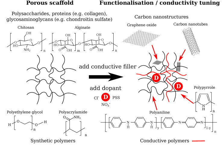
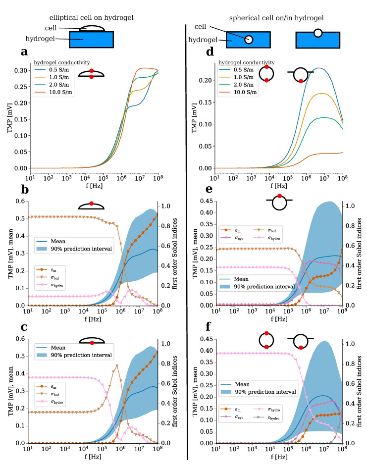
Cartilage regeneration is a clinical challenge. In recent years, hydrogels have emerged as implantable scaffolds in cartilage tissue engineering. Similarly, electrical stimulation has been employed to improve matrix synthesis of cartilage cells, and thus to foster engineering and regeneration of cartilage tissue. The combination of hydrogels and electrical stimulation may pave the way for new clinical treatment of cartilage lesions. To find the optimal electric properties of hydrogels, theoretical considerations and corresponding numerical simulations are needed to identify well-suited initial parameters for experimental studies. We present the theoretical analysis of a hydrogel in a frequently used electrical stimulation device for cartilage regeneration and tissue engineering. By means of equivalent circuits, finite element analysis, and uncertainty quantification, we elucidate the influence of the geometric and dielectric properties of cell-seeded hydrogels on the capacitive-coupling electrical field stimulation. Moreover, we discuss the possibility of cellular organisation inside the hydrogel due to forces generated by the external electric field. The introduced methodology is easily reusable by other researchers and allows to directly develop novel electrical stimulation study designs. Thus, this study paves the way for the design of future experimental studies using electrically conductive hydrogels and electrical stimulation for tissue engineering.
Keywords: biomaterial scaffolds; capacitive coupling; computational modelling; electrical stimulation; electrically conductive hydrogels; finite element analysis; scaffold; tissue engineering; uncertainty quantification.
Conflict of interest statement
The authors declare no conflict of interest.
Figures


Similar articles
-
Electrically conductive coatings in tissue engineering.Acta Biomater. 2024 Sep 15;186:30-62. doi: 10.1016/j.actbio.2024.08.007. Epub 2024 Aug 14. Acta Biomater. 2024. PMID: 39128796 Review.
-
Numerical Simulation of Electroactive Hydrogels for Cartilage-Tissue Engineering.Materials (Basel). 2019 Sep 9;12(18):2913. doi: 10.3390/ma12182913. Materials (Basel). 2019. PMID: 31505797 Free PMC article.
-
Computational study on electromechanics of electroactive hydrogels for cartilage-tissue repair.Comput Methods Programs Biomed. 2020 Dec;197:105739. doi: 10.1016/j.cmpb.2020.105739. Epub 2020 Sep 12. Comput Methods Programs Biomed. 2020. PMID: 32950923
-
Smart Polymeric Hydrogels for Cartilage Tissue Engineering: A Review on the Chemistry and Biological Functions.Biomacromolecules. 2016 Nov 14;17(11):3441-3463. doi: 10.1021/acs.biomac.6b01235. Epub 2016 Nov 3. Biomacromolecules. 2016. PMID: 27775329 Review.
-
Establishment of a New Device for Electrical Stimulation of Non-Degenerative Cartilage Cells In Vitro.Int J Mol Sci. 2021 Jan 1;22(1):394. doi: 10.3390/ijms22010394. Int J Mol Sci. 2021. PMID: 33401406 Free PMC article.
Cited by
-
Electrically Conductive Hydrogels for Articular Cartilage Tissue Engineering.Gels. 2022 Nov 3;8(11):710. doi: 10.3390/gels8110710. Gels. 2022. PMID: 36354618 Free PMC article. Review.
-
Strategies for Biomaterial-Based Spinal Cord Injury Repair via the TLR4-NF-κB Signaling Pathway.Front Bioeng Biotechnol. 2022 Apr 29;9:813169. doi: 10.3389/fbioe.2021.813169. eCollection 2021. Front Bioeng Biotechnol. 2022. PMID: 35600111 Free PMC article. Review.
-
Bizonal cardiac engineered tissues with differential maturation features in a mid-throughput multimodal bioreactor.iScience. 2022 Apr 26;25(5):104297. doi: 10.1016/j.isci.2022.104297. eCollection 2022 May 20. iScience. 2022. PMID: 35586070 Free PMC article.
-
Using a Digital Twin of an Electrical Stimulation Device to Monitor and Control the Electrical Stimulation of Cells in vitro.Front Bioeng Biotechnol. 2021 Dec 8;9:765516. doi: 10.3389/fbioe.2021.765516. eCollection 2021. Front Bioeng Biotechnol. 2021. PMID: 34957068 Free PMC article.
-
Electrical stimulation for cartilage tissue engineering - A critical review from an engineer's perspective.Heliyon. 2024 Sep 23;10(19):e38112. doi: 10.1016/j.heliyon.2024.e38112. eCollection 2024 Oct 15. Heliyon. 2024. PMID: 39416819 Free PMC article. Review.
References
-
- Zhao W., Jin X., Cong Y., Liu Y., Fu J. Degradable natural polymer hydrogels for articular cartilage tissue engineering. J. Chem. Technol. Biotechnol. 2013;88:327–339. doi: 10.1002/jctb.3970. - DOI
MeSH terms
Substances
Grants and funding
LinkOut - more resources
Full Text Sources
