. 2020 Nov 3;117(44):27245-27254.
doi: 10.1073/pnas.2008791117. Epub 2020 Oct 23.

Multiphase magnetism in Yb2Ti2O7

Affiliations

Multiphase magnetism in Yb2Ti2O7

Allen Scheie et al. Proc Natl Acad Sci U S A. .

Abstract

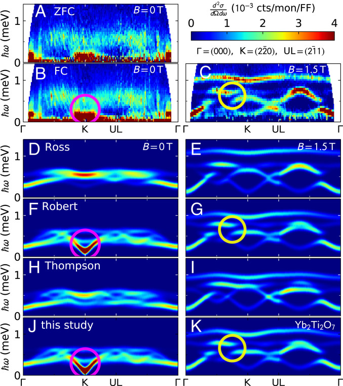
We use neutron scattering to show that ferromagnetism and antiferromagnetism coexist in the low T state of the pyrochlore quantum magnet [Formula: see text] While magnetic Bragg peaks evidence long-range static ferromagnetic order, inelastic scattering shows that short-range correlated antiferromagnetism is also present. Small-angle neutron scattering provides direct evidence for mesoscale magnetic structure that we associate with metastable antiferromagnetism. Classical Monte Carlo simulations based on exchange interactions inferred from [Formula: see text]-oriented high-field spin wave measurements confirm that antiferromagnetism is metastable within the otherwise ferromagnetic ground state. The apparent lack of coherent spin wave excitations and strong sensitivity to quenched disorder characterizing [Formula: see text] is a consequence of this multiphase magnetism.

Keywords: frustrated magnetism; neutron scattering; phase transitions; pyrochlore.


Conflict of interest statement

The authors declare no competing interest.

Figures

Fig. 1.
Fig. 1.
Refinement of Yb2Ti2O7 magnetic structure based on changes in integrated Bragg intensities upon cooling from 0.6 K to 80 mK in zero magnetic field. Inset shows the zero-field intensity of the (002) Bragg peak appears upon cooling from 300 to 80 mK, which rules out AIAO order. Note that the S(Q) axis is quadratic.
Fig. 2.
Fig. 2.
(A–K) Inelastic magnetic neutron scattering from Yb2Ti2O7 along Γ(000)K(22¯0)UL(21¯1)Γ(000) in (A) the B=0 ZFC state, (B) the B=0 FC state, and (C) B=1.5T, compared to linear spin wave theory predictions from (D and E) Ross et al.’s Hamiltonian (25), (F and G) Robert et al.’s Hamiltonian (26), (H and I) Thompson et al.’s Hamiltonian (20), and (J and K) this study. The vertical streaks in the zero-field data near Γ are due to saturated neutron detectors.
Fig. 3.
Fig. 3.
Fit to Yb2Ti2O7 spin wave spectrum. (A) Line through parameter space minimizing χ2 of the calculated vs. observed intensity data at 1.5 T. (B) Spin wave gap at (220) plotted against J2, with the star indicating a gap of 0.11 meV. The gap goes to zero at the phase boundary between the FM and the AFM Γ5 phase. (C) χ2 along the “best-fit line” in A. D–K show the measured neutron-scattering data and the calculated neutron-scattering cross-section for the Hamiltonian fitted to the 1.5-T data. The experimental plots are averaged over ±0.038 Å−1 in the direction perpendicular to the cut.
Fig. 4.
Fig. 4.
Calculated zero-field spin wave gap at (220) for Yb2Ti2O7 as a function of J1 and J2 for four Hamiltonians: (A) Ross et al. (25), (B) Robert et al. (26), (C) Thompson et al. (20), and (D) this study. White stars indicate the best fit parameters for each model. (J3 and J4 are held fixed to the best-fit values for each respective Hamiltonian. White areas are where neither the FM nor Γ5 AFM are stabilized. The spin-configuration energy was minimized for each point.) The gap goes to zero upon entering the Γ5 AFM ordered phase, and this study as well as that by Robert et al. (26) places Yb2Ti2O7 within error of the AFM phase boundary.
Fig. 5.
Fig. 5.
Inelastic magnetic neutron-scattering data for Yb2Ti2O7 compared to the calculated magnetic neutron-scattering cross-section for FM and AFM and mixed FM + AFM ground states. (A) Calculated magnetic neutron-scattering cross-section for the best-fit Hamiltonian FM ground state along high-symmetry directions Γ(000)K(22¯0)UL(21¯1)Γ(000). (B) Calculated spectrum for an AFM ψ3 state just across the phase boundary. (C) Average of FM and AFM spectra. (D) Field-cooled 70 mK spectrum. (E) Constant 0.2-meV energy slice for Yb2Ti2O7 (FC) at 70 mK scattering. (F and G) The 0.2-meV spin wave theory calculations for the FM and FM + AFM states, respectively. The overall scattering matches the AFM + FM result better, particularly near (43,23,23) at 0.2 meV.
Fig. 6.
Fig. 6.
(A and B) MC + LSWT calculated neutron spectrum for Yb2Ti2O7 (A) compared to the field-cooled 70 mK spectrum (B). (C–H) Constant energy (0.2 and 0.3 meV) slices for Yb2Ti2O7 (FC) at 70 mK scattering compared to the FM and MC + LSWT spectra. The MC + LSWT simulation better matches the scattering pattern, particularly near (43,23,23) at 0.2 meV.
Fig. 7.
Fig. 7.
(A) Spin wave gap at (22¯0) for Yb2Ti2O7 at 100 mK, plotted with the predicted gap from Robert et al. (26) and this study. (B) Zero-field spin wave spectrum around (22¯0) (following the same cuts as Fig. 3) measured at higher resolution. (C) Spin wave spectrum plotted against distance from (22¯0). (D and E) Calculated spin wave spectrum plotted against distance from (22¯0) for (D) a ferromagnetic ground state and (E) the MC + LSWT spectrum. Neither one reproduces the low-lying flat feature above (22¯0).
Fig. 8.
Fig. 8.
(A) SANS experimental configuration, with [11¯0] vertical and [111] along a horizontal magnetic field. (B–D) SANS data for Yb2Ti2O7 in (B) the zero-field–cooled state and (C) the field-cooled state after applying a 1-T field in the 111 direction and subtracting (D) a 1.5-K background. (E) Dependence of the (111) and (201) scattering streaks on wave vector transfer Q=(112¯) perpendicular to the plane of the detector, with 1.5-K data subtracted. Ranges of Q integrated are Q111=0.015±0.011 Å−1 and Q201=0.016±0.011 Å−1 shown in Fig. 10. (F) Difference between B and C, revealing an enhancement of (111) in the scattering rod after cooling in a field applied along that direction.
Fig. 9.
Fig. 9.
Field- and temperature-dependent SANS data for Yb2Ti2O7. (A–C) Temperature dependence of the (A) (111), (B) (11¯0), and (C) (201) rods at 0, 0.1, and 0.2 T. (D–F) Field dependence of the (D) (111), (E) (11¯0), and (F) (201) rods at 120 and 300 mK. The (111), (11¯0), and (201) directions are defined in the insets to Fig. 10 AC, Insets. (G–J) Colormap images of the Yb2Ti2O7 SANS pattern as a function of field at 100 mK.
Fig. 10.
Fig. 10.
Fits to SANS in Yb2Ti2O7. (AC) The Q-dependent scattering at various fields in the (A) (111), (B) (11¯0), and (C) (201) directions. The regions defining these directions are shown in A–C, Insets. (D and E) The results of a Porod exponent fit I=AQn.
Fig. 11.
Fig. 11.
Domain walls in Yb2Ti2O7 rotating through a Γ5 antiferromagnetic phase. Top image shows a domain wall between z and +z ferromagnetic domains, and Bottom image shows a domain wall between +x and +z, rotating between two states in the Γ5 manifold.

Comment in

  • On the way to understanding Yb2Ti2O7.
    Petit S. Petit S. Proc Natl Acad Sci U S A. 2020 Nov 24;117(47):29263-29264. doi: 10.1073/pnas.2020105117. Epub 2020 Nov 9. Proc Natl Acad Sci U S A. 2020. PMID: 33168710 Free PMC article. No abstract available.

References

    1. Keimer B., Moore J. E., The physics of quantum materials. Nat. Phys. 13, 1045–1055 (2017).
    1. Wen X. G., Niu Q., Ground-state degeneracy of the fractional quantum Hall states in the presence of a random potential and on high-genus Riemann surfaces. Phys. Rev. B 41, 9377–9396 (1990). - PubMed
    1. Löhneysen H. V., Rosch A., Vojta M., Wölfle P., Fermi-liquid instabilities at magnetic quantum phase transitions. Rev. Mod. Phys. 79, 1015–1075 (2007).
    1. Balents L., Spin liquids in frustrated magnets. Nature 464, 199–208 (2010). - PubMed
    1. Savary L., Balents L., Quantum spin liquids: A review. Rep. Prog. Phys. 80, 016502 (2016). - PubMed

Publication types

LinkOut - more resources