Review
. 2020 Aug 28;7(20):2001116.
doi: 10.1002/advs.202001116. eCollection 2020 Oct.

The Evolution of Flexible Electronics: From Nature, Beyond Nature, and To Nature

Affiliations
Review

The Evolution of Flexible Electronics: From Nature, Beyond Nature, and To Nature

Panpan Wang et al. Adv Sci (Weinh). .

Abstract

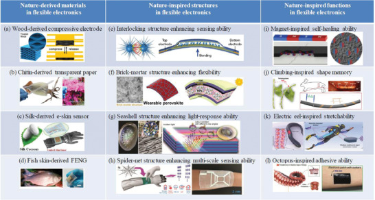
The flourishing development of multifunctional flexible electronics cannot leave the beneficial role of nature, which provides continuous inspiration in their material, structural, and functional designs. During the evolution of flexible electronics, some originated from nature, some were even beyond nature, and others were implantable or biodegradable eventually to nature. Therefore, the relationship between flexible electronics and nature is undoubtedly vital since harmony between nature and technology evolution would promote the sustainable development. Herein, materials selection and functionality design for flexible electronics that are mostly inspired from nature are first introduced with certain functionality even beyond nature. Then, frontier advances on flexible electronics including the main individual components (i.e., energy (the power source) and the sensor (the electric load)) are presented from nature, beyond nature, and to nature with the aim of enlightening the harmonious relationship between the modern electronics technology and nature. Finally, critical issues in next-generation flexible electronics are discussed to provide possible solutions and new insights in prospective exploration directions.

Keywords: energy storage; flexible electronics; flexible sensors; functional designs; nature.


Conflict of interest statement

The authors declare no conflict of interest.

Figures

Figure 1
Figure 1
An illustration of the close relationship between flexible electronics and nature from three aspects. From nature: Self‐healable fiber‐shaped supercapacitor. Reproduced with permission.[ 59 ] Copyright 2015, American Chemical Society. Environmental detecting sensor. Reproduced with permission.[ 60 ] Copyright 2018, Wiley‐VCH. Tri‐pathway wood‐based Li–O2 battery. Reproduced with permission.[ 61 ] Copyright 2019, Wiley‐VCH. Beyond nature: Highly stretchable supercapacitor. Reproduced with permission.[ 62 ] Copyright 2018, Springer Nature. Self‐powered touch/gesture tribo‐sensor. Reproduced with permission.[ 63 ] Copyright 2018, American Chemical Society. Smart electronic skin. Reproduced with permission.[ 23 ] Copyright 2018, Springer Nature. To nature: Transient rechargeable batteries. Reproduced with permission.[ 64 ] Copyright 2015, American Chemical Society. Fully water‐soluble sensor. Reproduced with permission.[ 65 ] Copyright 2018, American Chemical Society. Bioabsorbable capacitor. Reproduced with permission.[ 66 ] Copyright 2019, Wiley‐VCH.
Figure 2
Figure 2
Representative examples of nature‐derived materials, nature‐inspired structures and nature‐inspired functions in flexible electronics. Nature‐derived materials in flexible electronics: a) Wood‐derived compressive electrode. Reproduced with permission.[ 110 ] Copyright 2018, Elsevier. b) Chitin‐derived transparent paper. Reproduced with permission.[ 92 ] Copyright 2016, Wiley‐VCH. c) Silk‐derived e‐skin sensor. Reproduced with permission.[ 111 ] Copyright 2017, American Chemical Society. d) Fish skin‐derived FENG. Reproduced with permission.[ 112 ] Copyright 2017, American Chemical Society. Nature‐inspired structures in flexible electronics: e) Interlocking structure enhancing sensing ability. Reproduced under the terms of the CC‐BY Creative Commons Attribution 4.0 International License (https://creativecommons.org/licenses/by/4.0).[ 113 ] Copyright 2018, The Authors, published by Springer Nature. f) Brick‐mortar structure enhancing flexibility. Reproduced with permission.[ 114 ] Copyright 2019, The Royal Society of Chemistry. g) Seashell structure enhancing light‐response. Reproduced with permission.[ 115 ] Copyright 2019, Wiley‐VCH. h) Spider‐net structure enhancing multi‐scale sensing. Reproduced with permission.[ 116 ] Copyright 2019, Wiley‐VCH. Nature‐inspired functions in flexible electronics: i) Magnet‐inspired self‐healing ability. Reproduced with permission.[ 117 ] Copyright 2016, The Authors, published by American Association for the Advancement of Science. Reprinted/adapted from ref. [117]. © The Authors, some rights reserved; exclusive licensee American Association for the Advancement of Science. Distributed under a Creative Commons Attribution NonCommercial License 4.0 (CC B‐BNC) http://creativecommons.org/licenses/by-nc/4.0/. j) Climbing‐inspired shape memory ability. Reproduced with permission.[ 118 ] Copyright 2019, The Authors, published by American Association for the Advancement of Science. Reprinted/adapted from ref. [118]. © The Authors, some rights reserved; exclusive licensee American Association for the Advancement of Science. Distributed under a Creative Commons Attribution NonCommercial License 4.0 (CC BY‐NC) http://creativecommons.org/licenses/by-nc/4.0/. k) Electric eel‐inspired stretchability. Reproduced under the terms of the CC‐BY Creative Commons Attribution 4.0 International License (https://creativecommons.org/licenses/by/4.0).[ 119 ] Copyright 2019, The Authors, published by Springer Nature. l) Octopus‐inspired adhesive ability. Reproduced with permission.[ 35 ] Copyright 2018, Wiley‐VCH.
Figure 3
Figure 3
a) Graphical illustration of the structure evolution of natural balsa wood upon chemical treatment. b) Photograph and graphical illustration of the strain sensor connected with a LED light under compression and release conditions. a,b) Reproduced with permission.[ 110 ] Copyright 2018, Elsevier. c) Schematic illustration of the tree‐inspired tri‐pathway design for flexible Li–O2 cells. d) Morphology characterization of the flexible CNT‐coated wood membrane. e) Cross‐sectional SEM images of the CNT‐coated wood membrane showing the multichannel structure. c–e) Reproduced with permission.[ 61 ] Copyright 2019, Wiley‐VCH. f) Photograph (left) and SEM image (right) of red rose petals by supercritical drying. g) The sensing mechanism illustration of the natural‐material‐based e‐skin. h) The rose‐petal‐based e‐skin with real‐time monitoring of capacitance variations caused by repeated elbow bending. f–h) Reproduced with permission.[ 109 ] Copyright 2016, The Royal Society of Chemistry.
Figure 4
Figure 4
a) Illustration of a spider‐web‐inspired elastomer‐filled graphene woven fabric. b) Cross section of the freestanding graphene woven fabric. a,b) Reproduced with permission.[ 120 ] Copyright 2019, American Chemical Society. c) SEM image of ZnO particle with sea urchin‐shaped morphology. d) Schematics of a sensor made from a ZnO thin film sandwiched between two electrodes with highlights of the resistance modulation at local spine‐spine sites induced by mechanical stimuli. e) Schematics of the layered configuration in the sensor (top) and the bending state (bottom). c–e) Reproduced under the terms of the CC‐BY Creative Commons Attribution 4.0 International License (https://creativecommons.org/licenses/by/4.0).[ 113 ] Copyright 2018, The Authors, published by Springer Nature. f) Preparation of spirally layered elastomer. g) SEM (left) and optical images (right) of the elastomer. h) Self‐healing process of the spirally layered elastomer (top) and the reconstruction of conductive path (middle) in a circuit lightening a LED (bottom). f–h) Reproduced with permission.[ 121 ] Copyright 2019, Wiley‐VCH. i) Schematic configuration of the flexible tactile sensor. j) SEM image of a SWNTs/PDMS film with pyramid microstructure. k) The real‐time heart rate detection by simply attaching the sensor on a finger. l) Schematics of measuring the shear force when a constant force was applied on the sensor with certain scanning velocity. i–l) Reproduced with permission.[ 122 ] Copyright 2018, Wiley‐VCH.
Figure 5
Figure 5
a) Schematic of a solar‐powered smart watch embedded with self‐healing conductor. b) Schematic illustrating the healing mechanism of a metal conductor by a passivation film. a,b) Reproduced with permission.[ 143 ] Copyright 2018, Wiley‐VCH. c) Schematic diagram of the IS‐TENG. d) Digital photo of the as‐prepared, bifurcated, quadfurcated, and self‐healed IS‐TENG. c,d) Reproduced with permission.[ 144 ] Copyright 2017, Wiley‐VCH. e) Illustrative fabrication of a self‐healing supercapacitor. f) Photos of self‐healing electrode in a circuit with an LED bulb. e,f) Reproduced with permission.[ 149 ] Copyright 2014, Wiley‐VCH. g) Schematic components of the self‐healable yarn supercapacitor. h) Schematic illustration of the self‐healing process of the supercapacitor. g,h) Reproduced with permission.[ 59 ] Copyright 2015, American Chemical Society. i) Demonstration of the self‐healing process of the hydrogel electrolyte. j) Demonstration of the pristine and the self‐healed electrolyte supporting ≈500 g mass, respectively. k) Schematics of the supercapacitor comprising the self‐healing polyelectrolyte and PPy@CNT paper electrodes. l) Healing efficiency under different healing times. i–l) Reproduced under the terms of the CC‐BY Creative Commons Attribution 4.0 International License (https://creativecommons.org/licenses/by/4.0).[ 160 ] Copyright 2015, Springer Nature. m) Illustrative fabrication of the all‐in‐one self‐healing supercapacitor. Reproduced with permission.[ 161 ] Copyright 2018, The Royal Society of Chemistry.
Figure 6
Figure 6
a) Schematic of the self‐healing process of the Li‐ion battery based on self‐healing substrates. Reproduced with permission.[ 166 ] Copyright 2016, Wiley‐VCH. b) The schematic illustration of the self‐healability origin of PANa‐Fe3+ electrolyte. c) Photographs of the PANa‐Fe3+ hydrogel serving as anionic conductor successfully connecting the circuit before being cut and after autonomic healing. b,c) Reproduced with permission.[ 167 ] Copyright 2018, Wiley‐VCH. d) Schematic illustration of the flexible Li ion battery device. e) Schematic of excellent flexibility of the obtained electrode film. f) Photographs of an e‐watch powered by the battery before cutting, after cutting, and after self‐healing. d,e) Reproduced with permission.[ 168 ] Copyright 2018, Wiley‐VCH.
Figure 7
Figure 7
a) Schematic illustration of the hyper‐stretchable elastic‐composite generator. b) The elastic‐composite generator stretched by human hands. a,b) Reproduced with permission.[ 178 ] Copyright 2015, Wiley‐VCH. c) Photograph image of an actual SI‐TENG and its partially enlarged view. d) Demonstration of the SI‐TENG which can be stretched in any in‐plane direction and be rolled up. e) Schematic demonstrating the in‐plane tensile behaviors of the repeated rhombic unit in the SI‐TENG system. f) Schematic of the operation mechanism of the SI‐TENG. c–f) Reproduced with permission.[ 179 ] Copyright 2018, Wiley‐VCH.
Figure 8
Figure 8
a) An illustration of an ultra‐stretchable helix structured supercapacitor. b) Photographs of the supercapacitor with tensile strain from 0% to 850% to power the light emission diode. a,b) Reproduced with permission.[ 62 ] Copyright 2018, Springer Nature. c) Schematic illustration of the fabrication for stretchable supercapacitor utilizing the prestretching and release approach. d) Photographs of the LED light powered by supercapacitor devices at stretched states (ε = 150%). c,d) Reproduced with permission.[ 184 ] Copyright 2019, American Chemical Society. e) Supercapacitor with 1000% ultra‐stretchability. f) Capacitance enhancement with strain up to 1000%. g) Capacitance retention with increase of compression strain. e–g) Reproduced with permission.[ 185 ] Copyright 2017, Wiley‐VCH. h) Images of the supercapacitor under different tensile strains. i) The supercapacitor powering a red LED under compression. j) The supercapacitor powering a red LED under stretching. k) Capacitance retention of the supercapacitor during repeated tensile strain of 2000%. l) The arch bridged supercapacitor acting as a helmet worn on the head of an owl toy model to power a 3 V flexible LED strip. h–l) Reproduced with permission.[ 186 ] Copyright 2018, Wiley‐VCH.
Figure 9
Figure 9
a) Schematic illustration of a stretchable fiber‐shaped battery. b) Photograph of the battery being used to power a red LED before and after 200% stretching. c) Charging/discharging curves of the battery before and after 600% stretching. a–c) Reproduced with permission.[ 193 ] Copyright 2014, The Royal Society of Chemistry. d) Schematic illustration of a stretchable planar‐shaped Zn–air battery. e) Max power density curves under different tensile strains. f) Charging/discharging voltage plateau at different tensile strains. d–f) Reproduced with permission.[ 194 ] Copyright 2019, Wiley‐VCH.
Figure 10
Figure 10
a) Schematic illustration of the NiCo//Zn battery under 400% tensile strain and 50% compressive strain. b) Capacity enhancement ratio under tensile strain. c) Capacity retention under different compressive strain. a–c) Reproduced with permission.[ 196 ] Copyright 2019, Elsevier. d) Schematics of three kirigami patterns. e) Photograph of the battery under its fully stretched state. f) Photograph of the battery under its fully compact state. g) Capacity and coulombic efficiency under alternative states of compact and stretched states. h) The battery powering a smart watch at the compact state. i) The battery powering a smart watch at the stretched state. d–i) Reproduced under the terms of the CC‐BY Creative Commons Attribution 4.0 International License (https://creativecommons.org/licenses/by/4.0).[ 197 ] Copyright 2015, Springer Nature.
Figure 11
Figure 11
a) Schematic illustration of an all‐wood supercapacitor. Reproduced with permission.[ 209 ] Copyright 2017, The Royal Society of Chemistry. b) Schematic diagram and dissolution mechanism of the recyclable and green triboelectric nanogenerator. c) Dissolution process of each component. b,c) Reproduced with permission.[ 210 ] Copyright 2017, Wiley‐VCH. d) Digital, SEM, and schematic images of Zn degraded in PBS at 85 °C and digital images of the morphological evolution of Ti3C2 film triggered by medical H2O2. e) Digital images of the degradation process of Zn−MXene supercapacitor in PBS. External stimulus of medical H2O2 was added after the full degradation of Zn. f) Comparisons of degradation time and cycle number. d–f) Reproduced with permission.[ 212 ] Copyright 2019, American Chemical Society.
Figure 12
Figure 12
a) Structure of the as‐fabricated bioabsorbable supercapacitor. b) Implantation in the dorsal subcutaneous region of a SD rat (left) and pictures of the implanted site after different degradation time (right). c) CV curves of the implanted supercapacitor up to 50 days. d) In vivo biodegradation of the supercapacitor in a SD rat up to 6 months via micro‐CT imaging. a–d) Reproduced with permission.[ 66 ] Copyright 2019, Wiley‐VCH. e) The schematic illustration of the biodegradable battery. f) Optical images of the battery at various dissolution stages in PBS. g) In vivo degradation of the battery in the subcutaneous area of SD rat. e–g) Reproduced with permission.[ 219 ] Copyright 2018, Wiley‐VCH.
Figure 13
Figure 13
a) Fabrication of electrolyte and electrode for the flour‐based one‐stop supercapacitor. b) The stretching and self‐healing behavior of the electrolyte. c) The stretching and self‐healing behavior of the electrode. d) Photographs of the supercapacitor undergoing healing and different tensile strains after healing. e) CV curves from 0th healing to 40th healing. f) GCD curves of the supercapacitor from 0% to 50% stretch after healing. g) The biodegradation process of the supercapacitor in the simulated gastric fluid and nutritional soil. a–g) Reproduced with permission.[ 220 ] Copyright 2018, Elsevier.
Figure 14
Figure 14
Representative flexible sensors with functionality that from nature and beyond nature. From nature: the shape memory ability was represented by the shape memory polymers based mechanosensor. Reproduced with permission.[ 225 ] Copyright 2018, Wiley‐VCH. The sensing ability was represented by the artificial afferent nerve system. Reproduced with permission.[ 16 ] Copyright 2018, The Authors, published by American Association for the Advancement of Science. The self‐healing ability was represented by the multi‐functional self‐healable e‐skin. Reproduced with permission.[ 23 ] Copyright 2018, Springer Nature. The color‐changing ability was represented by the color‐shifting blooming flower. Reproduced with permission.[ 226 ] Copyright 2018, Wiley‐VCH. Beyond nature: the fully recyclable ability was represented by the fully recyclable and self‐healable e‐skin. Reproduced with permission.[ 52 ] Copyright 2018, The Authors, published by American Association for the Advancement of Science. Reprinted/adapted from ref. [52]. © The Authors, some rights reserved; exclusive licensee American Association for the Advancement of Science. Distributed under a Creative Commons Attribution NonCommercial License 4.0 (CC BY‐NC) http://creativecommons.org/licenses/by-nc/4.0/. The self‐powered ability was represented by the FENG‐based thin patch microphone. Reproduced with permission.[ 227 ] Copyright 2018, Springer Nature. The stretching ability was represented by the fully patterned intrinsically stretchable transistor. Reproduced with permission.[ 24 ] Copyright 2018, Springer Nature. The transparent ability was represented by the transparent tactile skin. Reproduced with permission.[ 228 ] Copyright 2017, Wiley‐VCH.
Figure 15
Figure 15
a) Schematic illustration of the impact of pH on molecular structure of PEDOT:PSS. b) Printable PEDOT:PSS/HPU inks, right is the 3D printing executed with a gel extruder on dry HPU films. a,b) Reproduced with permission.[ 255 ] Copyright 2018, Wiley‐VCH. c) Schematic illustration of Hg2+‐sensing FHCP‐4 film sensors that are immobilized onto a wide variety of materials. d) Photos of the emission color change of the hydrogel‐coated wearable sensing gloves when exposing the forefinger tip to Hg2+‐polluted sea shrimp. c,d) Reproduced with permission.[ 256 ] Copyright 2018, Wiley‐VCH. e) Schematic illustration of the skin surface wrinkling caused by excessive intake of ethanol. f) Schematic illustration of a smart wearable and flexible electronic device with a switchable and dynamic dual‐signal property. g) A proof‐of‐concept wearable device responds to ethanol vapor with a direct, dynamic visual and electrical feedback. e–g) Reproduced with permission.[ 257 ] Copyright 2019, Wiley‐VCH. h) Performance improvement of the wearable multisensory marine skin gadget with a reliable interlocking mechanism showing all the components. i) Scaled version without rigid components adhere strongly on goldfish attached using surgical glue. h,i) Reproduced with permission.[ 258 ] Copyright 2019, Wiley‐VCH.
Figure 16
Figure 16
a) Schematic illustration of the device configuration of fiber‐shaped p‐CuZnS/n‐TiO2 PD. b) Band diagram of the p‐CuZnS/n‐TiO2 heterojunction showing the photo generated carrier transfer process under UV illumination. c) The on‐off switching tests of the fiber‐shaped PD at 3 V under 350 nm. d) A wearable real‐time UV monitoring system in real life. a–d) Reproduced with permission.[ 60 ] Copyright 2018, Wiley‐VCH. e) The triboelectrification process between PDMS and PPy. f) The triboelectrification/photodetecting coupling process. g) The imaging process of retina. h) Schematic diagram of the measurement set. e–h) Reproduced with permission.[ 285 ] Copyright 2018, Wiley‐VCH. i) The outputing current of the e‐skin driven by blinking eyes. j) Schematic illustration of an OSSE integrating a flexible OTE generator with a paper substrate and an OFET‐based sensor. Right is the schematic illustration of the fabrication process of an OTE generator with PEDOT: PSS legs. k) Photographs of an OTE array powered chemical sensor. The right graphs show the sensing OFET and corresponding circuit diagram for the OSSE. l) Output voltage of an OTE array driven by a temperature difference created by a heating plate and a cooling flow, and the time monitoring of the current change in response to 1 ppm ammonia of the sensing OFET powered by the OTE array. i–l) Reproduced with permission.[ 286 ] Copyright 2019, Wiley‐VCH.
Figure 17
Figure 17
a) Schematic illustration of integrated self‐powered device with TENG, supercapacitor and strain sensor. b) Photograph of the vertically integrated self‐powered devices. c) Resistance change (ΔR/R 0) of the nanocomposite strain sensor versus time, measured by a source measurement unit, during breathing. a–c) Reproduced with permission.[ 291 ] Copyright 2015, American Chemical Society. d) Schematic illustration of the flexible weaving constructed self‐powered pressure sensor with SEM image of plasma‐etched PTFE nanowires and photograph of as‐fabricated SPS. e) Schematic diagram of the cross‐sectional view of the SPS single unit at original state and under pressure state with the electrical signal generation process illustration. f) SPS response time characterization. The response time was tested by periodically applying the pressure. g) Demonstration of the sensor system simultaneously monitoring the pulse waves from human fingertip and ear. d–g) Adapted with permission.[ 292 ] Copyright 2018, Wiley‐VCH. h) Scheme of the designed patch and theoretical working scenario. i) Battery model. j) Circuit operation when healthy sweat samples are analyzed. h–j) Reproduced under the terms of the CC‐BY Creative Commons Attribution 4.0 International License (https://creativecommons.org/licenses/by/4.0).[ 293 ] Copyright 2019, The Authors, published by Springer Nature.
Figure 18
Figure 18
a) Image of a transient hydration sensor. b) Images of the transient hydration sensor before and after dissolution for 2 days, respectively. a,b) Reproduced with permission.[ 296 ] Copyright 2014, Wiley‐VCH. c) Schematic illustration of a biodegradable pressure sensor. The inset shows the location of the Si nanowire strain gauge. d) Images of accelerated dissolution in a buffer solution (pH = 12) and a transparent PDMS enclosure at room temperature. e) Confocal fluorescence images of the cortical surface beneath the dissolved device at 2, 4, and 8 weeks, with glial fibrillary acidic protein (GFAP) to detect astrocytes (red), and ionized calcium‐binding adaptor molecule 1 (Iba1) to identify microglia/macrophages (green). The dashed line indicates the site of the implant. c–e) Reproduced with permission.[ 300 ] Copyright 2016. Springer Nature. f) Schematic diagram of the fully biodegradable strain and pressure sensor. g) Implanting the sensor on the back of a Sprague–Dawley rat. h) Pressure signal detection after 2 weeks of sensor implantation. f–h) Reproduced with permission.[ 301 ] Copyright 2018, Springer Nature.
Figure 19
Figure 19
a) Device architecture (ITO‐PET/RC‐LH1/Q0‐SCN/Au‐PET). b) Absorption spectrum of the RC‐LH1 pigment‐protein in solution. c) Energy diagram showing how photo excitation of the RC‐LH1complex (rainbow arrow) elicits an intraprotein charge separation (red arrows) and direct or Q0‐mediated charge transport to the electrodes (cyanarrows). d) The blend supports a VOC between the PET‐ITO and PET‐Au electrodes. e) Schematic of a touch stimulus moving continuously along the multipixel sensor. f) Touch tracking during tracing an L‐shape on the nine‐pixel sensor. a–f) Reproduced with permission.[ 305 ] Copyright 2018, Wiley‐VCH.

Similar articles

Cited by

References

    1. Lai Y. C., Deng J., Niu S., Peng W., Wu C., Liu R., Wen Z., Wang Z. L., Adv. Mater. 2016, 28, 10024. - PubMed
    1. Lee Y., Park J., Choe A., Cho S., Kim J., Ko H., Adv. Funct. Mater. 2019, 1904523.
    1. Hua Q., Sun J., Liu H., Bao R., Yu R., Zhai J., Pan C., Wang Z. L., Nat. Commun. 2018, 9, 244. - PMC - PubMed
    1. Boland J. J., Nat. Mater. 2010, 9, 790. - PubMed
    1. Meng B., Tang W., Too Z.‐H., Zhang X. S., Han M. D., Liu W., Zhang H. X., Energy Environ. Sci. 2013, 6, 3235.

LinkOut - more resources