. 2020 Sep 21;7(20):2001120.
doi: 10.1002/advs.202001120. eCollection 2020 Oct.

Addressable Acoustic Actuation of 3D Printed Soft Robotic Microsystems

Affiliations

Addressable Acoustic Actuation of 3D Printed Soft Robotic Microsystems

Murat Kaynak et al. Adv Sci (Weinh). .

Abstract

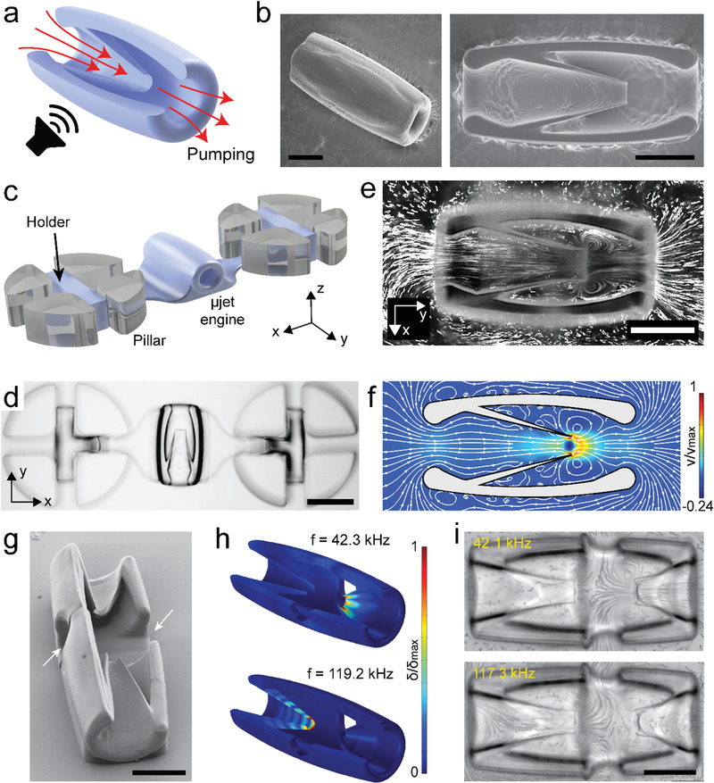
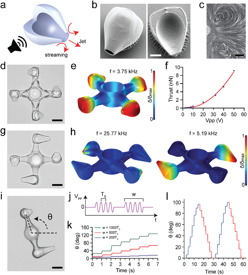
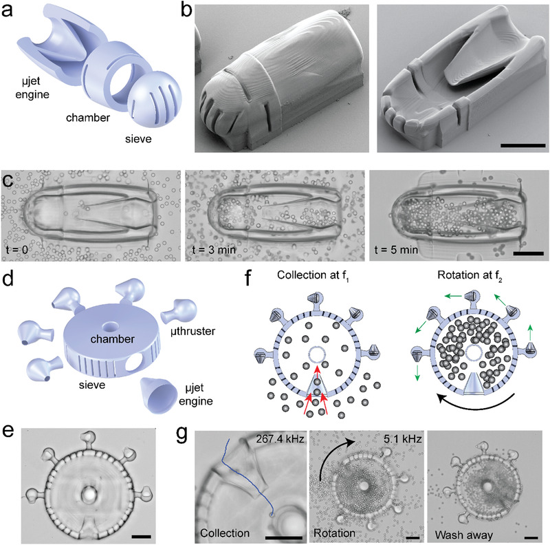
A design, manufacturing, and control methodology is presented for the transduction of ultrasound into frequency-selective actuation of multibody hydrogel mechanical systems. The modular design of compliant mechanisms is compatible with direct laser writing and the multiple degrees of freedom actuation scheme does not require incorporation of any specific material such as air bubbles. These features pave the way for the development of active scaffolds and soft robotic microsystems from biomaterials with tailored performance and functionality. Finite element analysis and computational fluid dynamics are used to quantitatively predict the performance of acoustically powered hydrogels immersed in fluid and guide the design process. The outcome is the remotely controlled operation of a repertoire of untethered biomanipulation tools including monolithic compound micromachinery with multiple pumps connected to various functional devices. The potential of the presented technology for minimally invasive diagnosis and targeted therapy is demonstrated by a soft microrobot that can on-demand collect, encapsulate, and process microscopic samples.

Keywords: acoustic waves; biomanipulation; direct laser writing; mechanical design; soft robotics.


Conflict of interest statement

The authors declare no conflict of interest.

Figures

Figure 1
Figure 1
The fabrication and operation of acoustically excited µjet engines. a) Schematic representation of the working principle of the µjet engine. The red arrows show the direction of pumping generated by acoustic streaming inside the device. b) Electron microscopy images showing fully (left) and partially (right) printed µjet engines. c) Illustration of the microfluidic test platform. The holder was printed along with the µjet engine to stabilize the motion. d) Representative bright‐field image of a 3D‐printed µjet engine that is anchored to pillars. e,f) Streamlines inside and around the µjet engine are visualized experimentally using fluorescent microparticles (e) and numerically using CFD simulations (f), respectively. The localized microstreaming around the tip of the conical wedge results in jet in the middle of the device. g) Electron microscopy image of the bidirectional µjet engine. The arrows show the outlets of the pump. h) Numerical simulations show addressable acoustic excitation of the µjet engine within the same device at different frequencies. Figure S5 in the Supporting Information shows corresponding images with exaggerated deformation. i) Streamlines showing the flow generated at the resonance frequency of each µjet engine. Scale bars: 75 µm in (b), (e), and (i) and 150 µm in (d).
Figure 2
Figure 2
The fabrication and operation of µthrusters. a) Schematic representation of the working principle. The red arrows show the direction of acoustic streaming and jet flow. b) Electron microscopy images of a fully (left) and partially (right) printed devices. c) Streamlines showing counter‐rotating vortices at the tip of a µthruster mounted inside the test chamber. d) Bright‐field image of a µrotor propelled by four µthrusters. The device was printed in situ around an elastomer pillar. e) Numerical simulation of the µrotor showing the eigenmode corresponding to the acoustic excitation frequency used in the experiments. Figure S6 in the Supporting Information shows corresponding images with exaggerated deformation. f) The calculated thrust of a µthruster with respect to input voltage used in the experiments. g) Bright‐field image of a bidirectional µrotor driven by two different designs of µthruster. The symmetric arrangement ensures smooth rotation. h) Numerical simulations showing selective excitation of µthrusters at different resonance frequencies. Figure S6 in the Supporting Information shows corresponding images with exaggerated deformation. i) Precise angular position control using pulse‐width modulation. j) The input signal consists of pulsed sine waves with period T S and frequency f S. The pulse width (w) was modulated while the amplitude and period of the pulse were kept constant. k) CCW rotation of the two‐arm µrotor exited with pulses of varying w. l) Bidirectional rotation of the device with pulse‐width modulation. CW rotation was performed at f S = 4.6 kHz and with w = 1000 T s while, for CCW rotation, the input signal was tuned to f S = 23.8 kHz and w = 1200 T s to generate identical motion in both directions. Scale bars: 15 µm in (b), 25 µm in (c), 50 µm in (d), (g), and (i).
Figure 3
Figure 3
Soft robotic micromanipulation with compound machinery. a) Schematic illustration and b) electron microscopy images of a collection device comprised of a µjet engine, a chamber with slits to facilitate fluid flow, and a sieve for size‐selective particle and cell encapsulation. Images in (b) show fully (left) and partially (right) printed devices. c) Time‐lapse microscopy images from a particle collection experiment showing: i) the initial condition where the microfluidic chamber was filled with particles and the chamber of the device is empty (t = 0), ii) an intermediary state where the chamber was gradually filled with particles due to the acoustic powering of the µjet engine at 117 kHz, and iii) the final state that showed the completely filled chamber after washing away the free particles. d) Schematic illustration and e) bright‐field image of a motorized collection device. Several µthrusters are located around the chamber for effective control over angular motion. f) Illustration summarizing the working principles of the device. Addressable actuation of µjet engine and µthrusters enable multiple degrees of freedom control over the operation. g) Image sequence showing particle collection at 267.4 kHz, rotation of the filled device at 5.1 kHz, and the final state of the device after cleaning of the free particles. Scale bars: 75 µm.

Similar articles

Cited by

References

    1. Sackmann E. K., Fulton A. L., Beebe D. J., Nature 2014, 507, 181. - PubMed
    1. Kearney C. J., Mooney D. J., Nat. Mater. 2013, 12, 1004. - PubMed
    1. Steiger C., Abramson A., Nadeau P., Chandrakasan A. P., Langer R., Traverso G., Nat. Rev. Mater. 2019, 4, 83.
    1. Wang Y., Kohane D. S., Nat. Rev. Mater. 2017, 2, 17020.
    1. Zhang H., Jackson J. K., Chiao M., Adv. Funct. Mater. 2017, 27, 1703606.

LinkOut - more resources