. 2021 Jan 21;14(2):595-613.
doi: 10.1002/cssc.202002113. Epub 2020 Nov 10.

Exploiting the Degradation Mechanism of NCM523 Graphite Lithium-Ion Full Cells Operated at High Voltage

Affiliations

Exploiting the Degradation Mechanism of NCM523 Graphite Lithium-Ion Full Cells Operated at High Voltage

Sven Klein et al. ChemSusChem. .

Abstract

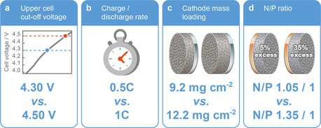
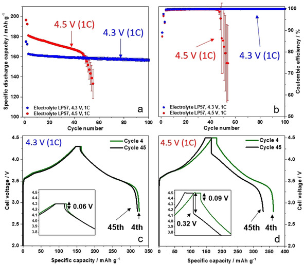
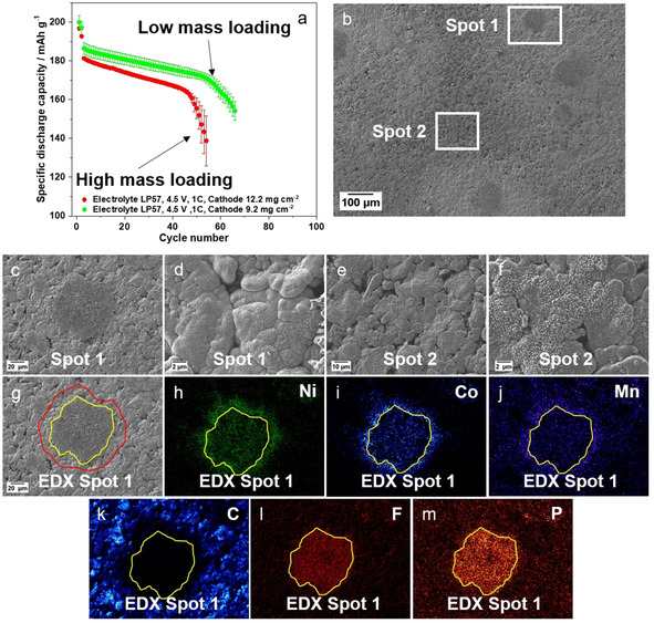
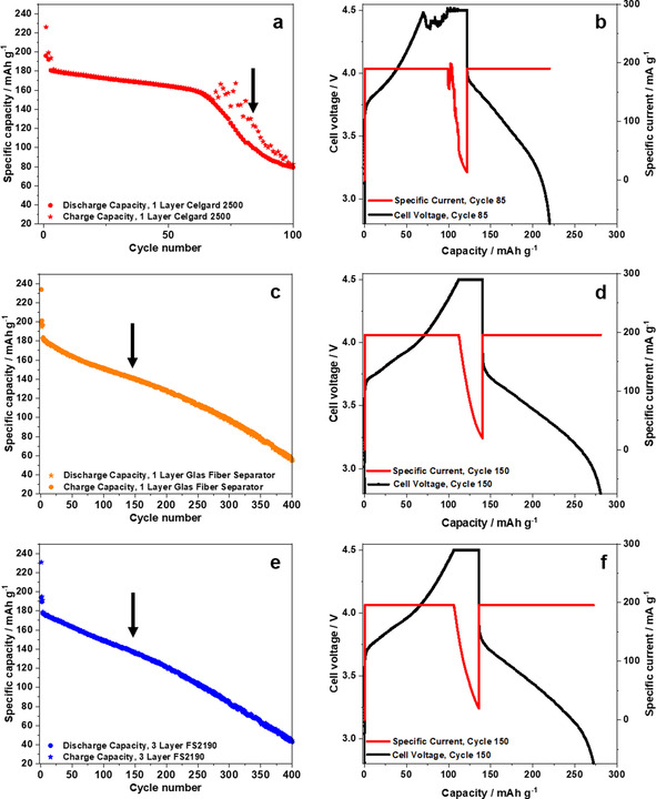
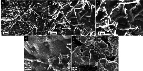
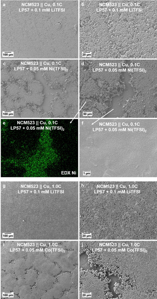
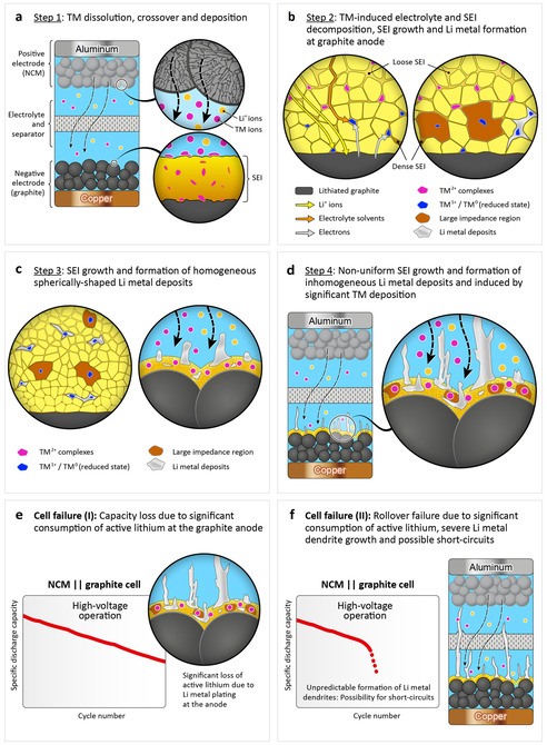
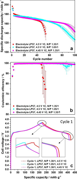
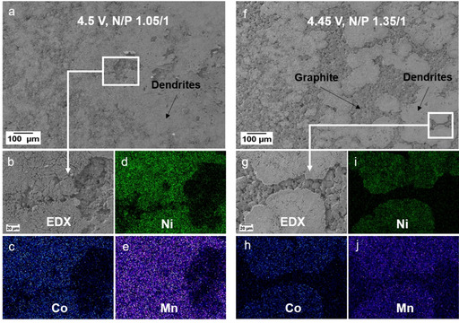
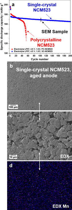
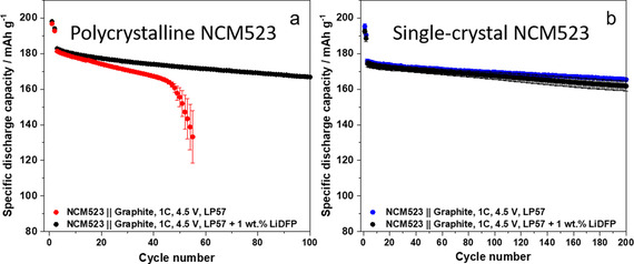
Layered oxides, particularly including Li[Nix Coy Mnz ]O2 (NCMxyz) materials, such as NCM523, are the most promising cathode materials for high-energy lithium-ion batteries (LIBs). One major strategy to increase the energy density of LIBs is to expand the cell voltage (>4.3 V). However, high-voltage NCM graphite full cells typically suffer from drastic capacity fading, often referred to as "rollover" failure. In this study, the underlying degradation mechanisms responsible for failure of NCM523 graphite full cells operated at 4.5 V are unraveled by a comprehensive study including the variation of different electrode and cell parameters. It is found that the "rollover" failure after around 50 cycles can be attributed to severe solid electrolyte interphase growth, owing to formation of thick deposits at the graphite anode surface through deposition of transition metals migrating from the cathode to the anode. These deposits induce the formation of Li metal dendrites, which, in the worst cases, result in a "rollover" failure owing to the generation of (micro-) short circuits. Finally, approaches to overcome this dramatic failure mechanism are presented, for example, by use of single-crystal NCM523 materials, showing no "rollover" failure even after 200 cycles. The suppression of cross-talk phenomena in high-voltage LIB cells is of utmost importance for achieving high cycling stability.

Keywords: degradation mechanisms; electrode materials; lithium-ion batteries; metal deposition; single-crystals.


Conflict of interest statement

The authors declare no conflict of interest.

Figures

Figure 1
Figure 1
Investigation of different electrode and cell parameters in high‐voltage NCM523 graphite full cells in regard of their impact on cell performance and transition metal deposition at the graphite anode: Impacts of (a) upper cutoff voltage (4.30 V vs. 4.50 V), (b) charge–discharge rate (at 4.50 V), (c) cathode mass loading (at 4.50 V), and (d) N/P capacity balancing ratio (at 4.50 V).
Figure 2
Figure 2
(a,b) Comparison of the charge‐discharge cycling performance of NCM523 graphite full cells (coin cells, two‐electrode configuration) in cell voltage ranges of 2.8–4.3 V and 2.8–4.5 V, showing (a) the discharge capacities and (b) the Coulombic efficiencies [cathode mass loading: 12.2 mg cm−2; charge–discharge cycling rate: 1 C (=170 mA g−1 at 4.3 V and=190 mA g−1 at 4.5 V); N/P ratio=1.35 / 1.00 at 4.5 V; 1.15 / 1.00 at 4.3 V and 1.50 / 1.00 at 4.3 V (see also Figure S3)]; (c,d) Corresponding charge–discharge cell voltage profiles of NCM523 graphite full cells in cell voltage ranges of (c) 2.8–4.3 V and (d) 2.8–4.5 V, showing selected cycles (4th and 45th cycle).
Figure 3
Figure 3
SEM/EDX analysis of graphite negative electrodes after 100 cycles in NCM523 graphite full cells (coin cells, two‐electrode configuration), as shown in Figure 2. (a‐c) SEM images of the graphite electrodes after cycling at 4.3 V; (d–f) SEM images of the graphite electrodes after cycling at 4.5 V. (g) Enlarged area of the SEM image in (e). (h–j) EDX elemental mappings of Ni (h), Co (i) and Mn (j) of the selected area of (g).
Figure 4
Figure 4
(a) Comparison of the charge–discharge cycling performance of NCM523 graphite full cells (coin cells, two‐electrode configuration) in a cell voltage range of 2.8–4.5 V (charge‐discharge rate: 1 C=190 mA g−1; N/P ratio=1.35 / 1.00) with NCM523 cathodes having a high mass loading (12.2 mg cm−2) and a low mass loading (9.2 mg cm−2). (b) SEM image of the graphite negative electrode after cycling (low mass loading cathode). (c–m) SEM images and EDX elemental mappings of the cycled graphite electrodes: (c) Spot 1 (dark grey dendrite spot); (d) spot 1 (highly covered graphite particles); (e,f) spot 2 (less covered graphite particles and no visible lithium dendrites); (g) selected dendrite island for EDX mapping (spot 1); (h–m) EDX elemental mappings of Ni (h), Co (i), Mn (j), carbon (k), fluorine (l), and phosphorus (m) for the selected area of (g).
Figure 5
Figure 5
(a,c,e) Comparison of the charge‐discharge cycling performance of NCM523 graphite full cells (coin cells, two‐electrode configuration) in a cell voltage range of 2.8–4.5 V (cathode mass loading: 12.2 mg cm−2; charge‐discharge cycling rate: 1 C (= 190 mA g−1 at 4.5 V); N/P ratio=1.35 / 1.00) using different separators: (a,b) 1 layer Celgard 2500, (c,d) 1 layer glass fiber separator (Whatman) and (e,f) 3 layers of a polyolefin separator (Freudenberg FS2190). (b,d,f) Cell voltage and specific current profiles of selected cycles.
Figure 6
Figure 6
SEM images of a highly covered graphite particle and subsequent Li metal dendrite growth at the graphite particle surface. Graphite electrode obtained after charge–discharge cycling (100 cycles) in NCM523 graphite full cells (cell voltage range: 2.8–4.5 V; charge–discharge rate: 1 C=190 mA g−1; N/P ratio=1.35 / 1.00, cathode mass loading: 12.2 mg cm−2).
Figure 7
Figure 7
SEM images of copper foils obtained after the first charge to 4.2 V (at 0.1 C or 1 C) in NCM523 Cu cells using different electrolytes: (a,b) LP57+0.1 mM LiTFSI electrolyte at 0.1 C; (c,d,f) LP57+0.1 mM Ni(TFSI)2 electrolyte at 0.1 C; (g, h) LP57+0.1 mM LiTFSI electrolyte at 1 C; (i,j) LP57+0.05 mM Co(TFSI)2 at 1 C. Section (e) shows the EDX elemental mapping of Ni from (d).
Figure 8
Figure 8
Schematic illustration of the major failure mechanisms in high‐voltage operated NCM graphite LIB cells. (a) Step 1: TM dissolution from the NCM cathode, crossover and subsequent TM deposition at the graphite anode; (b) Step 2: TM‐induced electrolyte and SEI alteration and Li metal formation at the anode, according to an ion‐exchange model.[ 37 , 39 , 64 ] Reaction pathways for electrolyte reduction (orange arrows) and direct “underpotential deposition” of Li metal (yellow arrows) is catalyzed by TM species in the reduced state, close to the surface of lithiated graphite.; [64] (c) Step 3: In an early state of charge–discharge cycling, the formation of homogeneous granular Li metal deposits is observed, likely involving a shielding mechanism;[ 60 , 61 ] (d) Step 4: In a later state of charge–discharge cycling, formation of inhomogeneous Li metal deposits (i. e., dendrites) is observed, which is a result of further SEI alteration and growth, induced by severe TM deposition at the graphite anode; (e,f) Two different cell failure mechanisms are proposed: (e) steady capacity loss due to significant consumption of active lithium, as a result of Li metal plating at the anode and (f) “rollover failure” (rapid capacity drop) due to severe formation of Li metal dendrites and the possible formation of (micro‐) short circuits due to dendrites growing to the cathode.
Figure 9
Figure 9
Comparison of the charge–discharge cycling performance of NCM523 graphite full cells (coin cells, two‐electrode configuration) in cell voltage ranges of 2.8–4.45 V (N/P=1.35 / 1.00) and 2.8–4.5 V (N/P=1.35 / 1.00 and 1.05 / 1.00). Cathode mass loading: 12.2 mg cm−2; charge–discharge cycling rate: 1 C [=185 mA g−1 at 4.45 V (N/P=1.35 / 1.00);=190 mA g−1 at 4.5 V (N/P=1.35 / 1.00);=190 mA g−1 at 4.5 V (N/P=1.05 / 1.00)]. (a) Discharge capacity and (b) Coulombic efficiency over cycling. (c) 1st cycle charge‐discharge cell voltage profiles at 4.45 V (N/P 1.35 / 1.00), 4.5 V (N/P 1.35 / 1.00) and 4.5 V (N/P 1.05 / 1.00).
Figure 10
Figure 10
SEM and EDX elemental mapping analysis of the graphite negative electrode after cycling in NCM523 graphite full cells (see Figure 9) in cell voltage ranges of (a–e) 2.8–4.5 V (N/P=1.05 / 1.00) and (f–j) 2.8–4.45 V (N/P=1.35 / 1.00). (a) SEM image of the graphite anode for the cell operated at 2.8–4.5 V (N/P=1.05 / 1.00); (b–e) the corresponding EDX elemental mappings of Ni (d), Co (c), and Mn (e). (f) SEM image of the graphite anode for the cell operated at 2.8–4.45 V (N/P=1.35 / 1.00); (g‐j) the corresponding EDX elemental mappings of Ni (i), Co (h), and Mn (j).
Figure 11
Figure 11
(a) Comparison of the charge–discharge cycling performance of NCM523 graphite full cells (coin cells, two‐electrode configuration) in a cell voltage range of 2.8–4.5 V (cathode mass loading: 12.2 mg cm−2; charge‐discharge rate: 1 C=190 mA g−1; N/P ratio=1.35 / 1.00) using either polycrystalline NCM523 and single‐crystal NCM523 cathode materials. (b,c) SEM images of the cycled graphite anodes of the single‐crystal NCM523 graphite full cells. (d) EDX elemental mapping of the cycled graphite anode (Mn).
Figure 12
Figure 12
Comparison of the charge–discharge cycling performance of NCM523 graphite full cells (coin cells, two‐electrode configuration) in a cell voltage range of 2.8–4.5 V (cathode mass loading: 12.2 mg cm−2; charge‐discharge rate: 1 C=190 mA g−1; N/P ratio=1.35 / 1.00) using either (a) polycrystalline NCM523 or (b) single‐crystal NCM523 cathode materials. Two different electrolyte systems are used: LP57 (pure) and LP57+1 wt.% LiDFP.

References

    1. Liu K., Li K., Peng Q., Zhang C., Front. Mech. Eng. 2019, 14, 47–64.
    1. Schmuch R., Wagner R., Hörpel G., Placke T., Winter M., Nat. Energy 2018, 3, 267–278.
    1. Zeng X., Li M., Abd El-Hady D., Alshitari W., Al-Bogami A. S., Lu J., Amine K., Adv. Energy Mater. 2019, 9, 1900161.
    1. Winter M., Barnett B., Xu K., Chem. Rev. 2018, 118, 11433–11456. - PubMed
    1. Betz J., Bieker G., Meister P., Placke T., Winter M., Schmuch R., Adv. Energy Mater. 2019, 9, 1803170.

LinkOut - more resources