. 2020 Oct 28;6(44):eabb0025.
doi: 10.1126/sciadv.abb0025. Print 2020 Oct.

Antibacterial infection and immune-evasive coating for orthopedic implants

Affiliations

Antibacterial infection and immune-evasive coating for orthopedic implants

Kyomin Chae et al. Sci Adv. .

Abstract

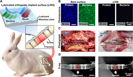
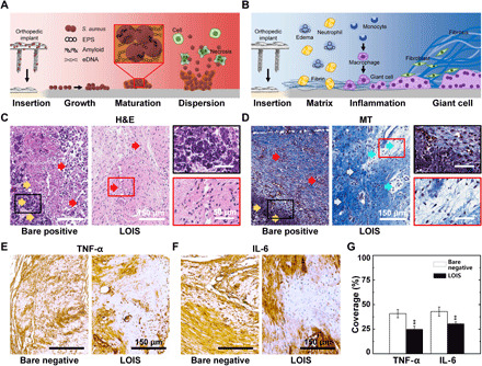
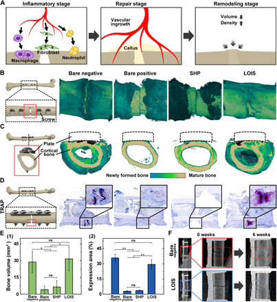
Bacterial infection and infection-induced immune response have been a life-threatening risk for patients having orthopedic implant surgeries. Conventional biomaterials are vulnerable to biocontamination, which causes bacterial invasion in wounded areas, leading to postoperative infection. Therefore, development of anti-infection and immune-evasive coating for orthopedic implants is urgently needed. Here, we developed an advanced surface modification technique for orthopedic implants termed lubricated orthopedic implant surface (LOIS), which was inspired by slippery surface of Nepenthes pitcher plant. LOIS presents a long-lasting, extreme liquid repellency against diverse liquids and biosubstances including cells, proteins, calcium, and bacteria. In addition, we confirmed mechanical durability against scratches and fixation force by simulating inevitable damages during surgical procedure ex vivo. The antibiofouling and anti-infection capability of LOIS were thoroughly investigated using an osteomyelitis femoral fracture model of rabbits. We envision that the LOIS with antibiofouling properties and mechanical durability is a step forward in infection-free orthopedic surgeries.


Figures

Fig. 1
Fig. 1. LOIS for antibiofouling orthopedic implants.
(A) Schematics of the LOIS and its implantation in rabbit femoral fracture model. (B) Fluorescence microscopy images of protein and bacterial biofilm on bare surface and LOIS substrate. (C) Photograph images and (D) x-ray images of the fracture site (highlighted with red rectangle) 4 weeks after implantation. Photo credit: Kyomin Chae, Yonsei University.
Fig. 2
Fig. 2. Fabrication process of LOIS and its characterization.
(A) Schematics of the four-step fabrication process of LOIS. The inset shows the SAM formed on the substrate. (B) SEM and AFM images for optimization of the micro/nanostructure of the substrate in different etching time. X-ray photoelectron spectroscopy (XPS) spectra of the (C) Cr2p and (D) F1s after surface passivation and SAM coating. a.u., arbitrary units. (E) Representative images of water droplet on bare, etched, SHP, and LOIS substrates. (F) Contact angle (CA) and SA measurement of liquids with different surface tension on SHP and LOIS. Data are presented as means ± SD.
Fig. 3
Fig. 3. Antibiofouling property of LOIS against bacteria, cell, protein, and calcium.
(A) Fluorescence microscopy images of each group (bare, etched, SHP, and LOIS) incubated in P. aeruginosa and MRSA suspension for 12 and 72 hours. (B) The number of adherent CFUs of P. aeruginosa and MRSA on each group of surfaces. (C) Schematics for antibiofouling mechanism of etched, SHP, and LOIS in the short and long term. (D) (1) Number of fibroblasts adhered on each substrate and fluorescence microscopy images of the cells adhered on bare and LOIS. (2) Adhesion test for immune-related protein, albumin, and calcium involved in bone healing process (*P < 0.05, **P < 0.01, ***P < 0.001, and ****P < 0.0001). ns, not significant.
Fig. 4
Fig. 4. Mechanical durability of LOIS.
(A) Schematics of (1) mechanical stress applied on the orthopedic implants during surgery and (2) optical image of the damaged orthopedic implant. (B) Schematics of nanomechanical property measurement via nanoindentation on bare surface and LOIS. (C) Nanoindentation force-displacement curves of bare surface and LOIS. (D) Optical images (the damaged areas highlighted with red rectangle) of different types of the orthopedic plates after ex vivo experiment to simulate the mechanical stress–causing damages during surgery. (E) Blood adhesion test and (F) protein adhesion test for the damaged orthopedic plate groups. (G) Measurement of the area coverage of protein adhered on the plates. (H) Optical images of the different types of orthopedic screws after ex vivo experiment. (I) Protein adhesion test to investigate the intactness of the different coatings. (J) Measurement of the area coverage of protein adhered on the screws. (K) Schematics of the rabbit’s movement, inducing fixation stress on fractured bone. (L) (1) Bending test results and optical images before and after bending. Difference of (2) Young’s modulus and (3) flexural strength in bare implant and SHP. Data are presented as means ± SD (*P < 0.05, **P < 0.01, ***P < 0.001, and ****P < 0.0001). Photo credit: Kyomin Chae, Yonsei University.
Fig. 5
Fig. 5. Histological analysis of tissues surrounding implants incubated in bacterial suspension for 12 hours.
(A) Schematics of the biofilm formation and spreading mechanism on the infected orthopedic implant’s surface. eDNA, extracellular DNAs. (B) Schematics of immune response upon the orthopedic implants’ insertion. (C) H&E staining and (D) MT staining of the tissues around the orthopedic implants of bare positive and LOIS. IHC of immune-related cytokines, (E) TNF-α and (F) IL-6, staining images of the rabbit implanted with bare negative and LOIS. (G) Quantification of the cytokine expression via area coverage measurements (**P < 0.01).
Fig. 6
Fig. 6. Analysis of the bone healing process based on micro-CT scan images and TRAP staining.
(A) Schematics of the bone healing process after fracture. (B) Difference in the degrees of callus formation and (C) cross-sectional images of the fracture site for each surface group. (D) TRAP staining to visualize osteoclast activity and bone resorption. Quantitative analysis of the callus formation outside of the cortical bone with (E) (1) micro-CT and (2) osteoclast activity based on TRAP activity. (F) X-ray images of the fractured bone of bare negative (highlighted with red dotted rectangle) and LOIS (highlighted with blue dotted rectangle) after 6 weeks of implantation. Statistical analysis was performed via one-way analysis of variance (ANOVA). *P < 0.05. **P < 0.01.

References

    1. White E., Lu D., Eyer B., Gottsegen C., Ahlmann E., Allison C., Gallery of uncommon orthopedic implants: A guide for emergency radiologist. Emerg. Radiol. 17, 227–247 (2010). - PubMed
    1. Barrère F., Mahmood T. A., De Groot K., Van Blitterswijk C. A., Advanced biomaterials for skeletal tissue regeneration: Instructive and smart functions. Mater. Sci. Eng. R Rep. 59, 38–71 (2008).
    1. Wu S., Liu X., Yeung K. W. K., Liu C., Yang X., Biomimetic porous scaffolds for bone tissue engineering. Mater. Sci. Eng. R Rep. 80, 1–36 (2014).
    1. Rony L., Lancigu R., Hubert L., Intraosseous metal implants in orthopedics: A review. Morphologie 102, 231–242 (2018). - PubMed
    1. Costerton J. W., Stewart P. S., Greenberg E. P., Bacterial biofilms: A common cause of persistent infections. Science 284, 1318–1322 (1999). - PubMed

Publication types

LinkOut - more resources