. 2020 Sep 29:11:577188.
doi: 10.3389/fphys.2020.577188. eCollection 2020.

Turbulent Systolic Flow Downstream of a Bioprosthetic Aortic Valve: Velocity Spectra, Wall Shear Stresses, and Turbulent Dissipation Rates

Affiliations

Turbulent Systolic Flow Downstream of a Bioprosthetic Aortic Valve: Velocity Spectra, Wall Shear Stresses, and Turbulent Dissipation Rates

Barna Becsek et al. Front Physiol. .

Abstract

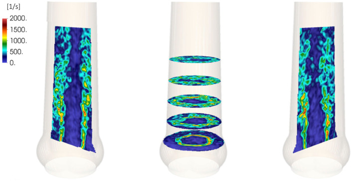
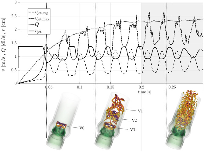
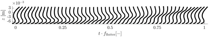
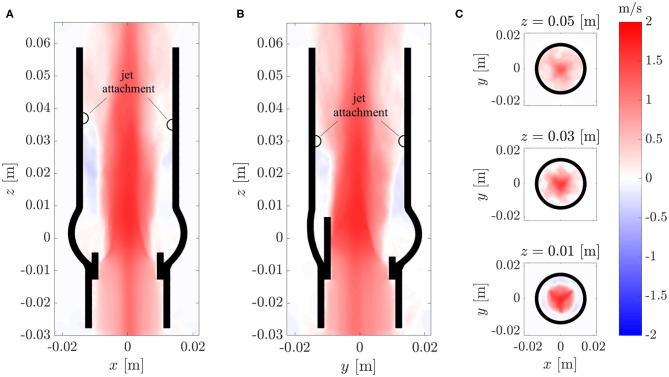
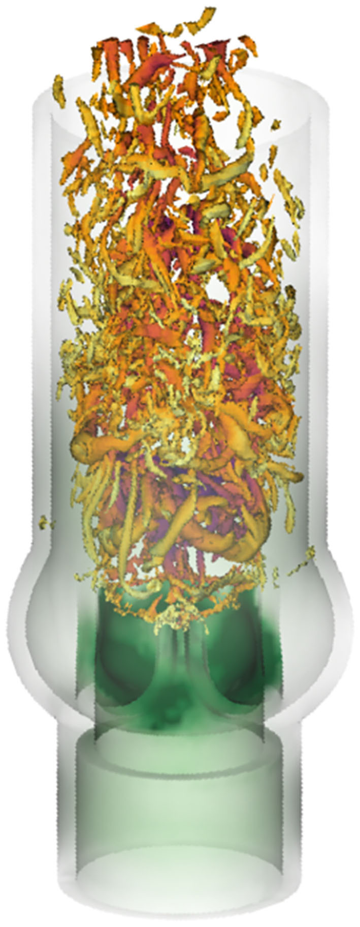
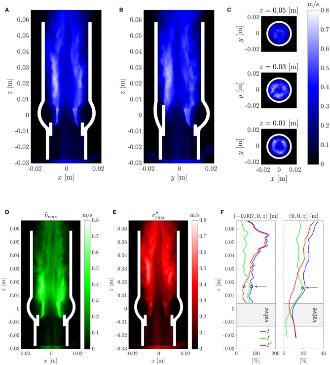
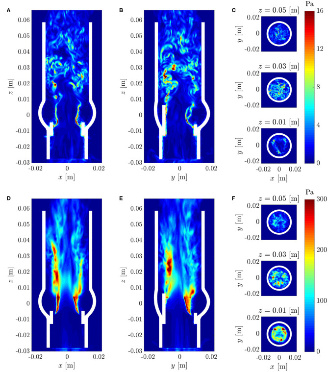
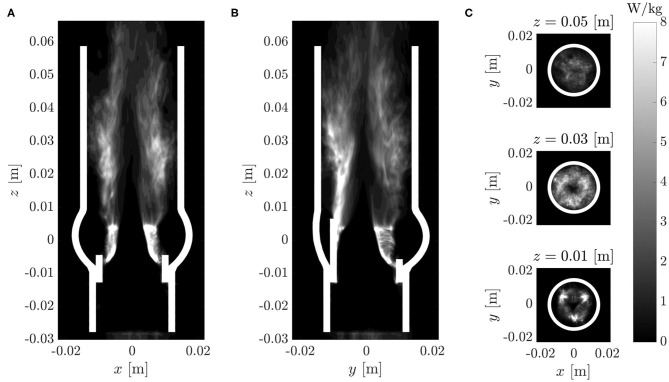
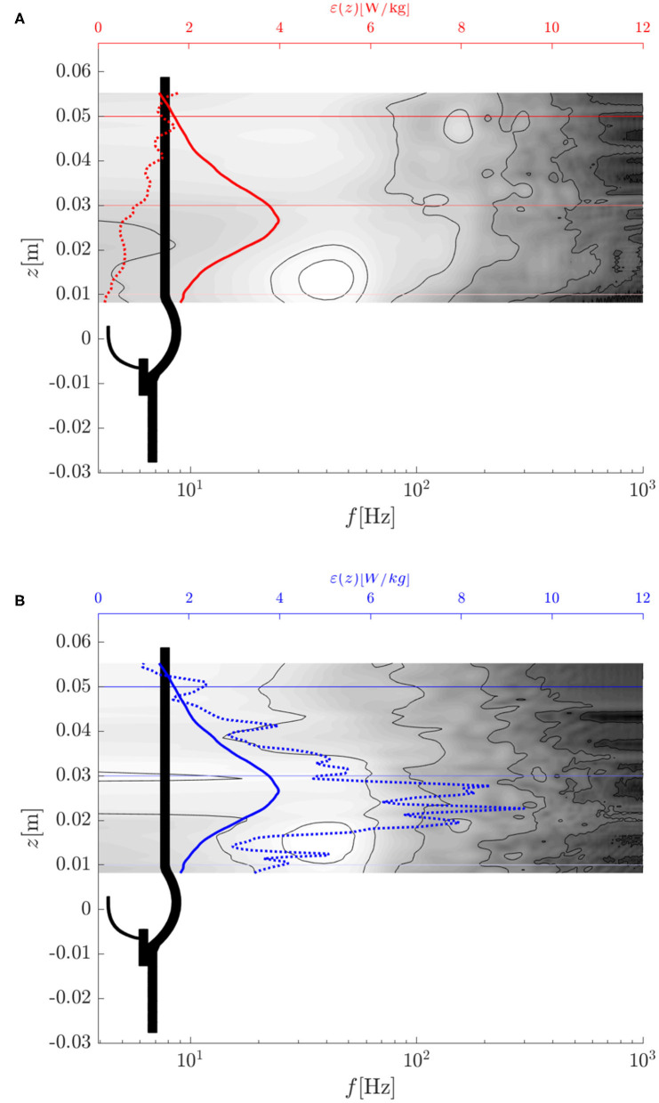
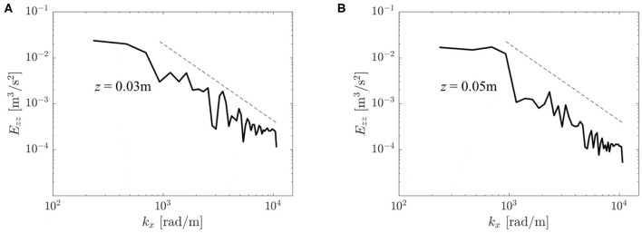
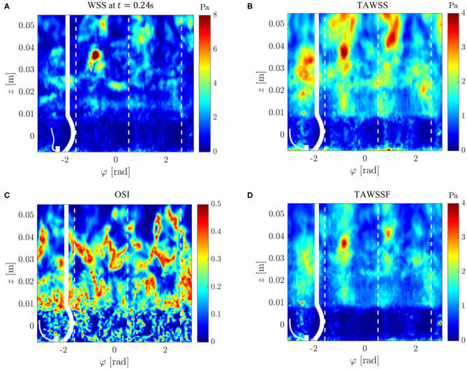
Every year, a quarter million patients receive prosthetic heart valves in aortic valve replacement therapy. Prosthetic heart valves are known to lead to turbulent blood flow. This turbulent flow field may have adverse effects on blood itself, on the aortic wall and on the valve performance. A detailed characterization of the turbulent flow downstream of a valve could yield better understanding of its effect on shear-induced thrombocyte activation, unphysiological wall shear stresses and hemodynamic valve performance. Therefore, computational simulations of the flow past a bioprosthetic heart valve were performed. The computational results were validated against experimental measurements of the turbulent flow field with tomographic particle image velocimetry. The turbulent flow was analyzed for disturbance amplitudes, dissipation rates and shear stress distributions. It was found that approximately 26% of the hydrodynamic resistance of the valve was due to turbulent dissipation and that this dissipation mainly took place in a region about one valve diameter downstream of the valve orifice. Farther downstream, the turbulent fluctuations became weaker which was also reflected in the turbulent velocity spectra of the flow field. Viscous shear stresses were found to be in the range of the critical level for blood platelet activation. The turbulent flow led to elevated shear stress levels along the wall of the ascending aorta with strongly fluctuating and chaotic wall shear stress patterns. Further, we identified leaflet fluttering at 40 Hz which was connected to repeated shedding of vortex rings that appeared to feed the turbulent flow downstream of the valve.

Keywords: bioprosthetic heart valve; computational fluid dynamics; fluid-structure interaction; laminar-turbulent transition; leaflet fluttering; thrombocyte activation; wall shear stress.


Figures

Figure 1
Figure 1
Shear rates in the systolic flow behind a BHV. Adapted from experimental results by Hasler and Obrist (2018).
Figure 2
Figure 2
Tri-leaflet bioprosthetic valve model: (A) photo of Edwards Intuity Elite 21 valve by Edwards Lifescience, Irvine, CA, USA, (B) CAD model of the valve, (C) fiber directions in the leaflet tissue, (D) dimensions of the valve model.
Figure 3
Figure 3
Geometry of the parameterized AR.
Figure 4
Figure 4
AR and valve model immersed in the fluid domain of size 45 × 45 × 97.5 mm with periodic boundary conditions in all spatial directions. The magenta shaded area indicates where a forcing term was applied.
Figure 5
Figure 5
Transient evolution of the characteristic quantities form Table 1. Vortical structures (orange λ2-isosurfaces, Jeong and Hussain, 1995) are shown at time instances t = 0.046 s, 0.125 s, and 0.24 s (indicated by vertical dotted lines).
Figure 6
Figure 6
Cross-section of a leaflet through its symmetry plane from base to trailing edge. Its fluttering motion is shown throughout one period of its fflutter = 40 Hz oscillation. The transversal deflections of the leaflet are shown to scale.
Figure 7
Figure 7
Axial component Vz of the mean flow field Vf in different cross-sections of the computational domains: (A) xz-plane, (B) yz-plane, (C) xy-plane.
Figure 8
Figure 8
Vortical structures at t = 0.24 s visualized by isosurfaces of the λ2-criterion by Jeong and Hussain (1995).
Figure 9
Figure 9
(A–C) Root-mean-square velocity fluctuations vrms in different cross-sections (same as in Figure 7). (D) Root-mean-square periodic fluctuations rms and (E) root-mean-square turbulent fluctuations vrms. (F) Turbulent intensities I and I″ and the intensity Ĩ of the periodic fluctuations along an axial line in the shear layer (left) and along the centerline (right). The arrows and circles indicate the position of the peak intensity Ĩ of the periodic fluctuations and the begin of the growth of the turbulence intensity I″ within the shear layer.
Figure 10
Figure 10
(A–C) Instantaneous maximum viscous shear stress τmax at t = 0.3 s; (D–F) Maximum Reynolds shear stress RSSmax (same cross-sections as in Figure 7).
Figure 11
Figure 11
Turbulent dissipation rate ϵ (same cross-sections as in Figure 7).
Figure 12
Figure 12
Turbulent dissipation rate ϵ (dotted lines), average turbulent dissipation rate ϵavg (solid lines) and temporal power spectral density of vf,z(x0,y0,z) (contour plot: white indicates high values, dark for low values): (A) along the center line (x0, y0, z) = (0, 0, z) m, (B) along a parallel line (x0, y0, z) = (−0.007, 0, z) m.
Figure 13
Figure 13
Velocity spectra Ezz(kx) at different locations in the flow field: (A) (x, y, z) = (0, 0, 0.03) m, (B) (x, y, z) = (0, 0, 0.05) m. The dashed line shows a −5/3 decay rate typical for a turbulent inertial subrange.
Figure 14
Figure 14
Wall shear stresses on the AR wall: (A) instantaneous WSS at t = 0.24 s, (B) mean WSS, (C) oscillating shear index OSI, (D) mean magnitude of WSS fluctuations. The values were projected onto an unrolled cylinder surface where the vertical dashed lines highlight the azimuthal locations of the valve posts.

References

    1. Alemu Y., Girdhar G., Xenos M., Sheriff J., Jesty J., Einav S., et al. . (2010). Design optimization of a mechanical heart valve for reducing valve thrombogenicity—a case study with ats valve. ASAIO J. 56, 389–396. 10.1097/MAT.0b013e3181e65bf9 - DOI - PubMed
    1. Aljalloud A., Shoaib M., Egron S., Arias J., Tewarie L., Schnoering H., et al. . (2018). The flutter-by effect: a comprehensive study of the fluttering cusps of the perceval heart valve prosthesis. Interact. Cardiovasc. Thorac. Surg. 27, 664–670. 10.1093/icvts/ivy162 - DOI - PubMed
    1. Armani D., Liu C., Aluru N. (1999). Re-configurable fluid circuits by pdms elastomer micromachining, in Technical Digest. IEEE International MEMS 99 Conference. Twelfth IEEE International Conference on Micro Electro Mechanical Systems (Cat. No. 99CH36291) (Orlando, FL: IEEE; ), 222–227.
    1. Auricchio F., Conti M., Ferrara A., Morganti S., Reali A. (2014). Patient-specific simulation of a stentless aortic valve implant: the impact of fibres on leaflet performance. Comput. Methods Biomech. Biomed. Eng. 17, 277–285. 10.1080/10255842.2012.681645 - DOI - PubMed
    1. Betts J. G, Young K. A., Wise J. A., Johnson E., Poe B., Kruse D. H., et al. (2013). Anatomy and Physiology. Houston, TX: OpenStax; Available online at: https://openstax.org/books/anatomy-and-physiology/pages/1-introduction