. 2020 Sep 25:14:570372.
doi: 10.3389/fnins.2020.570372. eCollection 2020.

Comparison of Muscle MEPs From Transcranial Magnetic and Electrical Stimulation and Appearance of Reflexes in Horses

Affiliations

Comparison of Muscle MEPs From Transcranial Magnetic and Electrical Stimulation and Appearance of Reflexes in Horses

Sanne Lotte Journée et al. Front Neurosci. .

Abstract

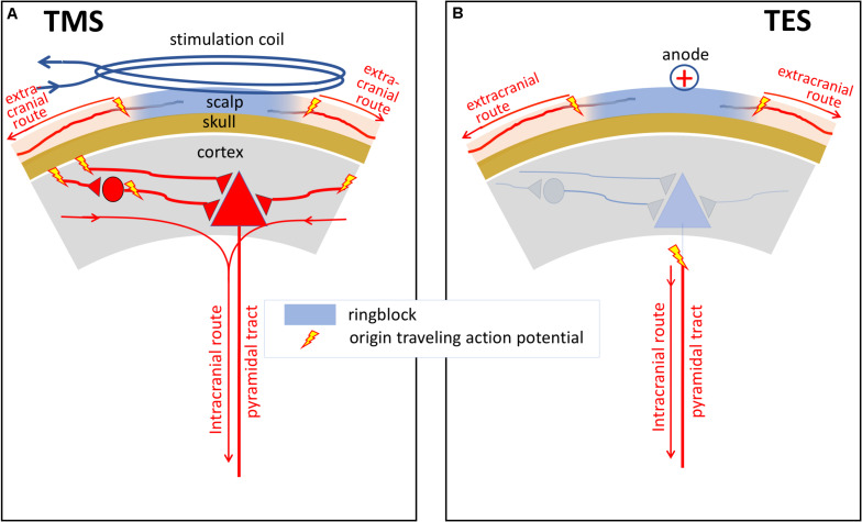
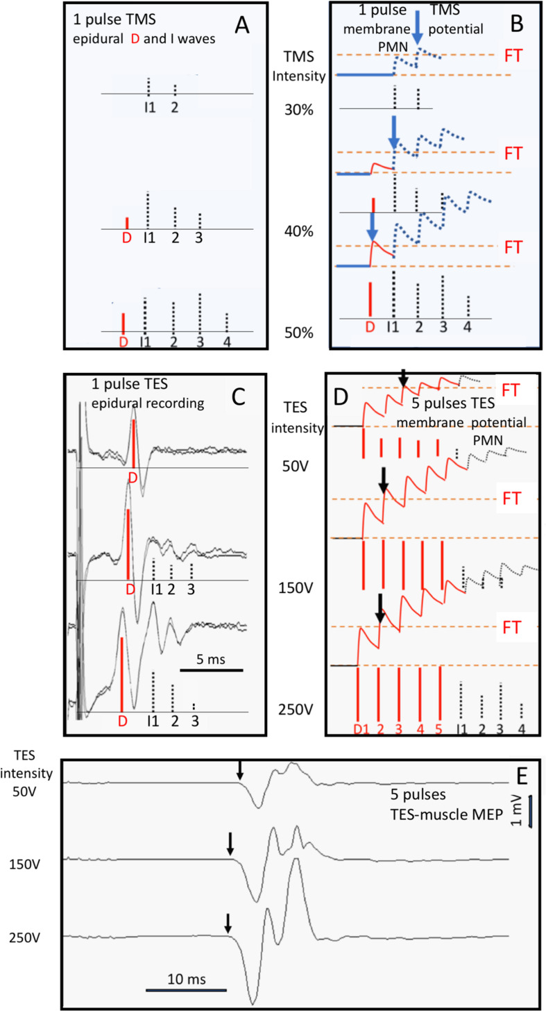
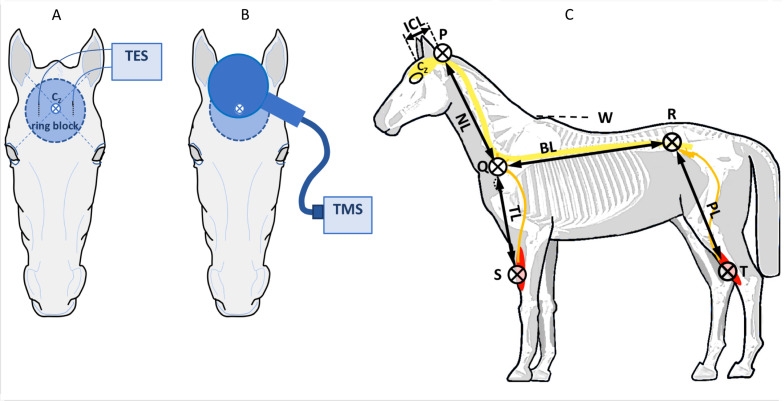
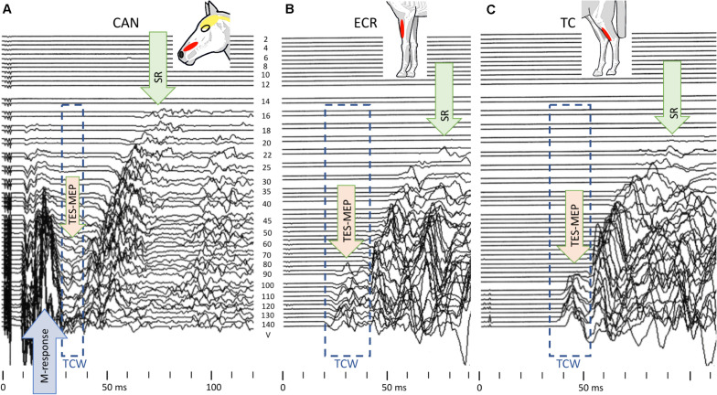
Introduction: Transcranial electrical (TES) and magnetic stimulation (TMS) are both used for assessment of the motor function of the spinal cord in horses. Muscular motor evoked potentials (mMEP) were compared intra-individually for both techniques in five healthy horses. mMEPs were measured twice at increasing stimulation intensity steps over the extensor carpi radialis (ECR), tibialis cranialis (TC), and caninus muscles. Significance was set at p < 0.05. To support the hypothesis that both techniques induce extracranially elicited mMEPs, literature was also reviewed.

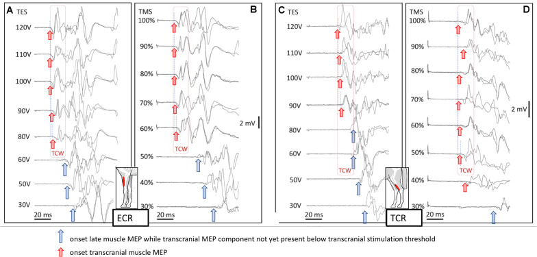
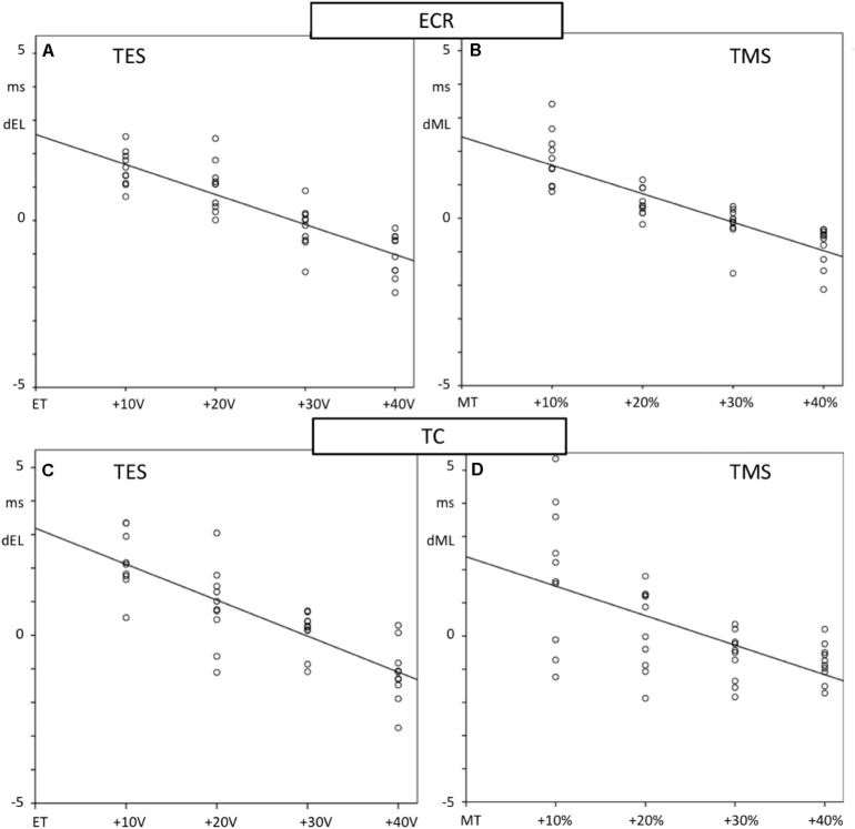
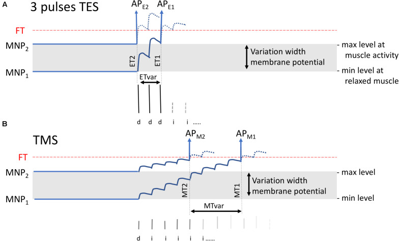
Results: Both techniques show the presence of late mMEPs below the transcranial threshold appearing as extracranially elicited startle responses. The occurrence of these late mMEPs is especially important for interpretation of TMS tracings when coil misalignment can have an additional influence. Mean transcranial motor latency times (MLT; synaptic delays included) and conduction velocities (CV) of the ECR and TC were significantly different between both techniques: respectively, 4.2 and 5.5 ms (MLT TMS --MLT TES ), and -7.7 and -9.9 m/s (CV TMS -CV TES ). TMS and TES show intensity-dependent latency decreases of, respectively, -2.6 (ECR) and -2.7 ms (TC)/30% magnetic intensity and -2.6 (ECR) and -3.2 (TC) ms/30V. When compared to TMS, TES shows the lowest coefficients of variation and highest reproducibility and accuracy for MLTs. This is ascribed to the fact that TES activates a lower number of cascaded interneurons, allows for multipulse stimulation, has an absence of coil repositioning errors, and has less sensitivity for varying degrees of background muscle tonus. Real axonal conduction times and conduction velocities are most closely approximated by TES.

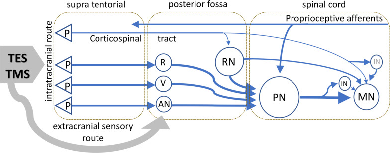
Conclusion: Both intracranial and extracranial mMEPs inevitably carry characteristics of brainstem reflexes. To avoid false interpretations, transcranial mMEPs can be identified by a stepwise latency shortening of 15-20 ms when exceeding the transcranial motor threshold at increasing stimulation intensities. A ring block around the vertex is advised to reduce interference by extracranial mMEPs. mMEPs reflect the functional integrity of the route along the brainstem nuclei, extrapyramidal motor tracts, propriospinal neurons, and motoneurons. The corticospinal tract appears subordinate in horses. TMS and TES are interchangeable for assessing the functional integrity of motor functions of the spinal cord. However, TES reveals significantly shorter MLTs, higher conduction velocities, and better reproducibility.

Keywords: TES; TMS; horses; motor potentials; neurology; startle reflex; transcranial stimulation.


Figures

FIGURE 1
FIGURE 1
Schematic illustrations of differences between sites of activation and neural processing of neural elements under a TMS coil (A) and under anodal stimulation in TES (B) in human and primates. The major action of TES is to stimulate corticospinal tract axons directly, probably in the subcortical white matter. In contrast, the major action of TMS is the excitation of intracortical axons, which then cause indirect, transynaptic excitation of corticospinal and other corticofugal neurons. The curved lines with arrows show the intra- and extracranial routes of action potentials from the onset of axonal activation. Activation of the extracranial axons occurs outside the ring block.
FIGURE 2
FIGURE 2
Human data visualizing the relation between D- and I-waves of TMS (A,B) and TES (C–E) mMEPs and the shortening effects on MLTs at three stimulation intensities: respectively, 30, 40, and 50% for TMS and 50, 150, and 250 V for TES. The vertical arrows in E point at the MLTs of the mMEPs. D-waves are indicated by red vertical bars and I-waves by gray bars. (A) Bars for which the height represents the size of epidural D- and I-waves from single-pulse TMS are reconstructed from the epidural recordings of Kaneko et al. (1996) (C) intra-operative epidural MEP at single-pulse TES and (E) mMEP response at five pulses per train; ipi = 1.3 ms. (B,D) are artist impressions of the course of EPSP summations of the MN membrane potentials depicted in graphs (A,C). (C–E) Belong to a clinical patient (Department of Neurosurgery, UMCG, University of Groningen, Netherlands) under propofol/sufentanil anesthesia during intra-operative monitoring with (C) single-pulse TES epidural descending volleys and (E) multipulse TES mMEP recordings with five pulses per train of the same patient; ipi = 1.3 ms. The vertical arrows in panels (B,D) indicate the first crossings of the imaginary EPSP stair function (the abortion of the stair function by a transition into a firing action potential is not visualized for didactic reasons) at the FT.
FIGURE 3
FIGURE 3
Placement of TES needle electrodes (A) and TMS coil (B) on the head of a horse. The vertex is defined at the cross-section of connecting lines between the ears and contralateral eyes. Circular area: ring block. (C) Anatomic landmarks for estimation of the axonal lengths in the spinal cord and peripheral nerves: P, occipital protuberance; Q, anterior rim of the scapula near corpus C7; R, dorso-ventral point of the hip; S, upper electrode ECR; T, upper electrode TC. ICL, intracranial segment length; NL, neck length 7 cervical corpora; BL, back length between Q and R; TL, length peripheral nerve limb; PL, length peripheral nerve hind limb.
FIGURE 4
FIGURE 4
Landscape plots of muscle mMEPs of the m. ECR (A,B) and m. TC (C,D) at TES (A,C) and TMS (B,D). TS thresholds: ET = 80 V (ECR) and 90 V (TC); MT = 60% (ECR) and 50% (TC). The TCW are indicated by the dashed box contour lines. The up-pointing arrows indicate the onset of transcranial or extracranial late mMEPs as described by the legend in the figure.
FIGURE 5
FIGURE 5
TES-mMEP landscape plots of the TES-mMEPs of the CAN (A), ECR (B), and TC (C) muscle groups illustrating the close relationship between stimulation threshold voltages of caninus muscle (CAN) responses (M-response) from extracranial elicited facial nerve axons (A) and the also assumed extracranial elicited SRs (example from case 4). Stimulation thresholds: M-response: 16 V, SR: for CAN 14 V; ECR and TC 22 V, and TES-mMEP all muscle groups: 80–90 V. Note that the TCW of the CAN mMEPs is smaller than for the two mMEP series due to squeezing by leading M-responses elicited by direct activation of facial nerve axons.
FIGURE 6
FIGURE 6
Scatter plots showing the regression lines of MLTs of fore limb (A,B) and hind limb (C,D) mMEPs and TS intensities of TES (A,C) and TMS (B,D). The TES increases are given as voltage differences with the stimulation thresholds of ET for electrical and as percentage differences with MT for magnetic stimulation. Differences with mean MLTs, dEL for TES and dML for TMS, are plotted vertically and TS-intensities horizontally. Slopes of the regression lines m with correlation R and significance are specified in Table 1. All regression lines show significant decreasing courses.
FIGURE 7
FIGURE 7
Visualization of expected variations of the MLT for three-pulse TES (A) and single-pulse TMS (B) when MNPs vary between a resting state at MNP1 to a facilitated state at MNP2. TES or TMS generate superimposed EPSP stair functions. The model applies to horses when assuming the presence of a corticospinal connection. In practice, the stair-wise course is likely smoothed when synaptic delays of interneurons evolve asynchronously with interpulse intervals. The EPSP stairs result from the contribution of a sequence of D- and I-waves that mainly are transducted by IN and PN but likely less pronounced via monosynaptic connections to MNs as far as these may exist in horses. APE1 and APM1 are the action potentials arising at the FT level that belong to the MNP1 membrane potential while APE2 and APM2 belong to MNP2. ETvar and MTvar are the latency variations between ET1 and ET2 and between MT1 and MT2, respectively. The model predicts for TES lower MLTs with smaller variations (ETvar) than in TMS, which is explained from the steep flank resulting from three initial large D-wave amplitudes.
FIGURE 8
FIGURE 8
Schematic visualization of the important motor tracts of TS pertaining to TES and TMS as expected in ungulates as horses. The scheme is speculative because no specific anatomic data on horses is available. TMS and TES activate transcranially supra tentorial located axons and also extracranial sensory axons connected to neurons in the brain stem and upper cervical regions. The extracranial connections, as indicated by the gray arrow, are mediated via sensory axons of cranial nerves and possibly high cervical roots and conveyed to the neural network of activated brain stem reflexes. The proprioceptive nucleus PN at C3-C4 has a major integrating role of motor tracts departing from the brain stem from different neurons of which RN are reticular neurons, R the nucleus ruber, V neurons of vestibular nuclei, which receive connections from the pyramidal neurons in the cortex, and AN indicates additional nuclei that mediate other, such as tectospinal, connections from subcortical axons to spinal motor tracts. The PN possibly also receives collaterals from corticospinal tracts. Retrograde connections of the PN to the brain stem and cerebellum are not shown. The MN receive inputs from the PN, RN, and when it applies, directly from the corticospinal or via IN. The possibility of direct connections with MN from remaining brain stem neurons is not incorporated in the diagram. Latency times of TMS and TES reflect the functional tracts that are pivotal in motor control.

Similar articles

Cited by

References

    1. Alstermark B., Isa T., Pettersson L.-G., Sasaki S. (2007). The C3-C4 propriospinal system in the cat and monkey: a spinal pre-motoneuronal centre for voluntary motor control. Acta Physiol. 189 123–140. 10.1111/j.1748-1716.2006.01655.x - DOI - PubMed
    1. Alstermark B., Ogawa J., Isa T. (2004). Lack of monosynaptic corticomotoneuronal EPSPs in rats: disynaptic EPSPs mediated via reticulospinal neurons and polysynaptic EPSPs via segmental interneurons. J. Neurophysiol. 91 1832–1839. 10.1152/jn.00820.2003 - DOI - PubMed
    1. Álvarez-Blanco S., Leon L., Valls-Solé J. (2009). The startle reaction to somatosensory inputs: different response pattern to stimuli of upper and lower limbs. Exp. Brain Res. 195 285–292. 10.1007/s00221-009-1784-7 - DOI - PubMed
    1. Amassian V. E., Cracco R. Q., Maccabee P. J. (1989). Focal stimulation of human cerebral cortex with the magnetic coil: a comparison with electrical stimulation. Electroencephalogr. Clin. Neurophysiol. 74 401–416. 10.1016/0168-5597(89)90029-4 - DOI - PubMed
    1. Amassian V. E., Eberle L., Maccabee P. J., Cracco R. Q. (1992). Modelling magnetic coil excitation of human cerebral cortex with a peripheral nerve immersed in a brain-shaped volume conductor: the significance of fiber bending in excitation. Electroencephalogr. Clin. Neurophysiol. 85 291–301. 10.1016/0168-5597(92)90105-k - DOI - PubMed

LinkOut - more resources