. 2019 May;6(5):647-661.
doi: 10.1364/optica.6.000647. Epub 2019 May 10.

Computational aberration compensation by coded-aperture-based correction of aberration obtained from optical Fourier coding and blur estimation

Affiliations

Computational aberration compensation by coded-aperture-based correction of aberration obtained from optical Fourier coding and blur estimation

Jaebum Chung et al. Optica. 2019 May.

Abstract

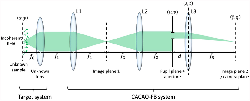
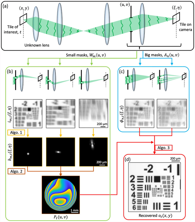
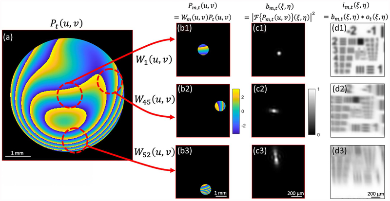
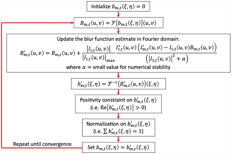
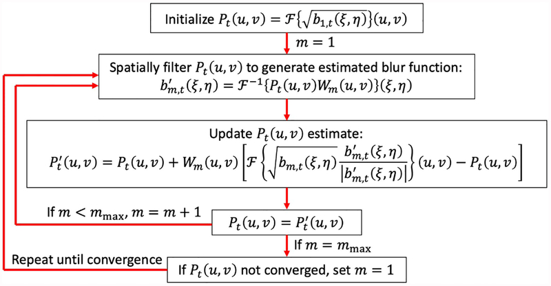
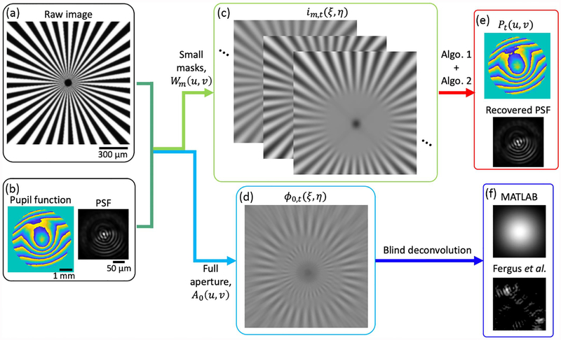
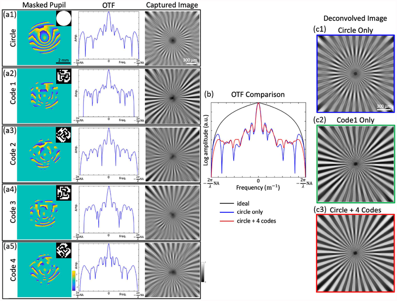
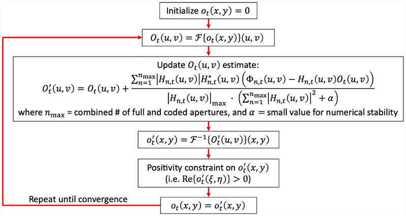
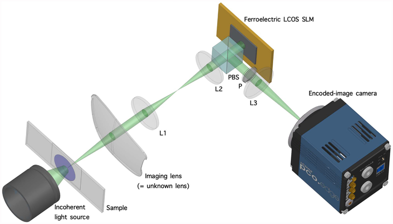
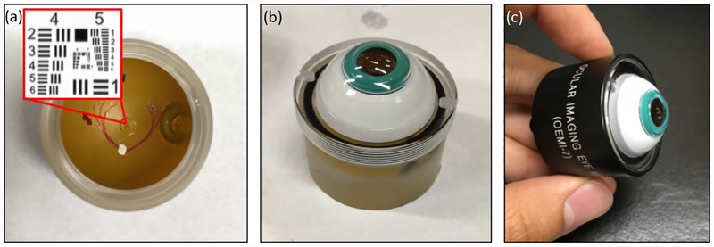
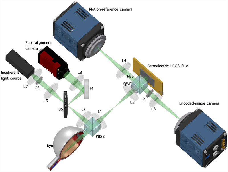
We report a novel generalized optical measurement system and computational approach to determine and correct aberrations in optical systems. The system consists of a computational imaging method capable of reconstructing an optical system's pupil function by adapting overlapped Fourier coding to an incoherent imaging modality. It recovers the high-resolution image latent in an aberrated image via deconvolution. The deconvolution is made robust to noise by using coded apertures to capture images. We term this method coded-aperture-based correction of aberration obtained from overlapped Fourier coding and blur estimation (CACAO-FB). It is well-suited for various imaging scenarios where aberration is present and where providing a spatially coherent illumination is very challenging or impossible. We report the demonstration of CACAO-FB with a variety of samples including an in vivo imaging experiment on the eye of a rhesus macaque to correct for its inherent aberration in the rendered retinal images. CACAO-FB ultimately allows for an aberrated imaging system to achieve diffraction-limited performance over a wide field of view by casting optical design complexity to computational algorithms in post-processing.


Figures

Fig. 1.
Fig. 1.
Optical architecture of CACAO-FB. The CACAO-FB system consists of three tube lenses (L1, L2, and L3) to relay the image from the target system for analysis. The target system consists of an unknown lens and an unknown sample with spatially incoherent field. The CACAO-FB system has access to the conjugate plane of the target system’s pupil, which can be arbitrarily modulated with binary patterns using a spatial light modulator. The images captured by the CACAO-FB system are intensity only. f0, f1, f2, and f3 are the focal lengths of the unknown lens, L1, L2, and L3, respectively. d is an arbitrary distance smaller than f3.
Fig. 2.
Fig. 2.
Outline of CACAO-FB pipeline. (a) The captured images are broken into small tiles of isoplanatic patches (i.e., aberration is spatially invariant within each tile). (b) Data acquisition and post-processing for estimating the pupil function Pt(u, v). Limited-aperture images im,t(ξ, η) are captured with small masks, Wm(u, v) applied at the pupil plane. Local PSFs bm,t(ξ, η) are determined by the blur estimation procedure, Algorithm 1. These PSFs are synthesized into the full-aperture pupil function Pt(u, v) with Fourier-ptychography-based alternating projections algorithm, Algorithm 2. (c) Data acquisition with big masks An(u, v) at the pupil plane. (d) The recovered Pt(u, v) from (b) and the big-aperture images ϕn,t(ξ, η) from (c) are used for deconvolution (Algorithm 3) to recover the latent aberration-free intensity distribution of the sample ot(x, y).
Fig. 3.
Fig. 3.
Simulating image acquisition with different small masks at the pupil plane. (a) The full pupil function masked by the lens’s NA-limited aperture. Differently masked regions of the pupil, (b1)–(b3), give rise to different blur kernels, (c1)–(c3), which allows us to capture images of the sample under the influence of different PSFs. Only the phase is plotted for Pt(u, v) and Pm,t(u, v)s, and their apertures are marked by the black boundaries. W1(u, v), W45(u, v), and W52(u, v) are three small masks from a spiraling-out scanning sequence.
Fig. 4.
Fig. 4.
Flowchart of Algorithm 1: blur estimation algorithm for determining local PSFs from images captured with small apertures Wm,t(u, v).
Fig. 5.
Fig. 5.
Flowchart of Algorithm 2: Fourier-ptychography-based alternating projections algorithm for reconstructing the unknown lens’s pupil function Pt(u, v).
Fig. 6.
Fig. 6.
Simulation of our pupil function recovery procedure and a comparison with blind deconvolution algorithms. (a) The Siemens star pattern used in the simulation. (b) The system’s pupil function and the associated PSF. (c) A series of images im,t(ξ, η)s captured with small masks Wm(u, v) applied to the pupil function. (d) An image captured with the full-pupil-sized mask An(u, v) on the pupil function, which simulates the general imaging scenario by an aberrated imaging system. (e) The system’s pupil function and PSF recovered by our procedure. They show high fidelity to the original functions in (b). (f) Blur functions recovered by MATLAB’s and Fergus et al.’s blind deconvolution algorithm, respectively. They both show poor reconstructions compared to the recovered PSF in (e).
Fig. 7.
Fig. 7.
Simulation that demonstrates the benefit of coded-aperture-based deconvolution. (a1)–(a5) Masked pupil functions obtained by masking the same pupil function with the full circular aperture and coded apertures under different rotation angles (0°, 45°, 90°, 135°), their associated OTFs along one spatial frequency axis, and captured images. Each coded aperture is able to shift the null regions of the OTF to different locations. (b) Comparison between the OTF of a circular-aperture-masked pupil function and the summed OTFs of the circular- and coded-aperture-masked pupil functions. Null regions in the frequency spectrum are mitigated in the summed OTF, which allows all the frequency content of the sample within the band limit to be captured with the imaging system. The OTF of an ideal pupil function is also plotted. (c1) Deconvolved image with only a circular aperture shows poor recovery with artifacts corresponding to the missing frequency contents in the OTF’s null regions. (c2) A recovered image using one coded aperture only. Reconstruction is better than (c1) but still has some artifacts. (c3) A recovered image using circular and multiple coded apertures is free of artifacts since it does not have missing frequency contents.
Fig. 8.
Fig. 8.
Flowchart of Algorithm 3: iterative Tikhonov regularization for recovering the latent sample image ot(x, y) from the aberrated images. Here, Φn,t(u, v)=F{ϕn,t(ξ, η)}(u, v).
Fig. 9.
Fig. 9.
Experimental setup of imaging a sample with a crude lens (i.e., unknown lens). Sample is illuminated by a monochromatic LED (520 nm), and the lens’s surface is imaged onto the SLM by a 1∶1 lens relay. The part of light modulated by the SLM is reflected by the PBS and is further filtered by a polarizer to account for the PBS’s low extinction ratio in reflection (1:20). The pupil-modulated image of the sample is captured on the sCMOS camera. L, lens; P, polarizer; PBS, polarizing beam splitter.
Fig. 10.
Fig. 10.
Resolution performance measured by imaging a Siemens star target. (a) A crude lens has optical aberration that prevents resolving the Siemens star’s features. (b) CACAO-FB is able to computationally remove the aberration and resolve 19.6 μm periodicity feature size, which lies between the coherent and incoherent resolution limit given by the focal length of 130 mm, the aperture diameter of 5.5 mm, and the illumination wavelength of 520 nm. (c) Pupil function recovered by CACAO-FB used for removing the aberration. (d) The PSF associated with the pupil function. (e) Intensity values from the circular traces on (a) and (b) that correspond to the minimum resolvable feature size of 19.6 μm periodicity. The Siemens star’s spokes are not visible in the raw image’s trace, whereas 40 cycles are clearly resolvable in the deconvolved result’s trace.
Fig. 11.
Fig. 11.
Spatially varying aberration compensation result on a grid of USAF target. (a) The full FOV captured by our camera with the full circular aperture at 5.5 mm displayed on the SLM. Each small region denoted by (b), (c), and (d) had a different aberration map as indicated by varying pupil function and PSFs. Spatially varying aberration is adequately compensated for in post-processing as shown by the deconvolution results (b2), (c2), and (d2).
Fig. 12.
Fig. 12.
Eye model with a USAF target embedded on the retinal plane. (a) A cut-out piece of glass of USAF target is attached on the retina of the eye model. The lid simulates the cornea and also houses a lens element behind it. (b) The model is filled with water with no air bubbles in its optical path.(c) The water-filled model is secured by screwing it in its case.
Fig. 13.
Fig. 13.
Experimental setup of imaging an eye model and an in vivo eye. Illumination is provided by a fiber-coupled laser diode (520 nm), and the eye’s pupil is imaged onto the SLM by a 1∶1 lens relay. The sample is slightly defocused from the focal length of the crude lens to add additional aberration into the system. Pupil alignment camera provides fiduciary to the user for adequate alignment of the pupil on the SLM. PBS2 helps with removing corneal reflection. The motion-reference camera is synchronized with encoded-image camera to capture images not modulated by the SLM. BS, beam splitter; L, lens; M, mirror; P, polarizer; PBS, polarized beam splitter; QWP, quarter-wave plate.
Fig. 14.
Fig. 14.
CACAO-FB result of imaging the USAF target in the eye model. (a) Raw image (2560 × 1080 pixels) averaged over 12 frames captured with the full circular aperture at 4.5 mm. The pupil function and PSF in each boxed region show the spatially varying aberration. (b)–(d) Deconvolution results show sharp features of the USAF target. The uneven background is from the rough surface of the eye model’s retina.
Fig. 15.
Fig. 15.
Showing the importance of masked pupil kernel shape determination for successful deconvolution. (a1)–(a3) Limited PSFs determined only by considering their centroids. (b) Recovered aberration and deconvolution result obtained with centroid-only limited PSFs. Some features of USAF are distorted. (c1)–(c3) Limited PSFs determined with the blur estimation algorithm. (d) Recovered aberration and deconvolution result obtained with the blur-estimated local PSFs. No distortions in the image are present, and more features of the USAF target are resolved.
Fig. 16.
Fig. 16.
CACAO-FB result from imaging an in vivo eye of a rhesus macaque. (a) Raw image averaged over 213 frames captured with 4.5 mm full circular aperture. (b) Deconvolution result using the (c) pupil function reconstructed by CACAO-FB procedure. (d) PSF associated with the pupil function.

Similar articles

Cited by

References

    1. Lohmann AW, Dorsch RG, Mendlovic D, Zalevsky Z, and Ferreira C, “Space-bandwidth product of optical signals and systems,”J. Opt. Soc. Am. A 13, 470–473 (1996).
    1. McConnell G, Trägårdh J, Amor R, Dempster J, Reid E, and Amos WB, “A novel optical microscope for imaging large embryos and tissue volumes with sub-cellular resolution throughout,” eLife 5, e18659 (2016). - PMC - PubMed
    1. Godara P, Dubis A, Roorda A, Duncan J, and Carroll J, “Adaptive optics retinal imaging: Emerging clinical applications,” Optom. Vis. Sci 87, 930–941 (2010). - PMC - PubMed
    1. Williams D, “Imaging single cells in the living retina,” Vis. Res 51, 1379–1396 (2011). - PMC - PubMed
    1. Fried DL, “Anisoplanatism in adaptive optics,” J. Opt. Soc. Am 72, 52–61 (1982).

LinkOut - more resources