. 2020 Nov 2;12(11):2574.
doi: 10.3390/polym12112574.

Polymer Microchannel and Micromold Surface Polishing for Rapid, Low-Quantity Polydimethylsiloxane and Thermoplastic Microfluidic Device Fabrication

Affiliations

Polymer Microchannel and Micromold Surface Polishing for Rapid, Low-Quantity Polydimethylsiloxane and Thermoplastic Microfluidic Device Fabrication

Chia-Wen Tsao et al. Polymers (Basel). .

Abstract

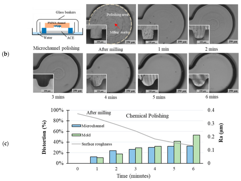
Polymer-based micromolding has been proposed as an alternative to SU-8 micromolding for microfluidic chip fabrication. However, surface defects such as milling marks may result in rough microchannels and micromolds, limiting microfluidic device performance. Therefore, we use chemical and mechanical methods for polishing polymer microchannels and micromolds. In addition, we evaluated their performance in terms of removing the machining (milling) marks on polymer microchannel and micromold surfaces. For chemical polishing, we use solvent evaporation to polish the sample surfaces. For mechanical polishing, wool felt polishing bits with an abrasive agent were employed to polish the sample surfaces. Chemical polishing reduced surface roughness from 0.38 μm (0 min, after milling) to 0.13 μm after 6 min of evaporation time. Mechanical polishing reduced surface roughness from 0.38 to 0.165 μm (optimal pressing length: 0.3 mm). As polishing causes abrasion, we evaluated sample geometry loss after polishing. Mechanically and chemically polished micromolds had optimal micromold distortion percentages of 1.01% ± 0.76% and 1.10% ± 0.80%, respectively. Compared to chemical polishing, mechanical polishing could better maintain the geometric integrity since it is locally polished by computer numerical control (CNC) miller. Using these surface polishing methods with optimized parameters, polymer micromolds and microchannels can be rapidly produced for polydimethylsiloxane (PDMS) casting and thermoplastic hot embossing. In addition, low-quantity (15 times) polymer microchannel replication is demonstrated in this paper.

Keywords: PDMS casting; microchannel; micromilling; micromold; polymer microfabrication; polymer microfluidics; polymer polishing; thermoplastic hot embossing.


Conflict of interest statement

The authors declare no conflict of interest.

Figures

Figure 1
Figure 1
Schematic of (a) rapid microchannel prototyping through direct milling for both (b) mechanical and chemical polishing. (c) shows polymer micromold replication for both (d) mechanical and chemical polishing setup. (e) displays photographs of the experimental the setup.
Figure 2
Figure 2
Surface roughness of polymethyl methacrylate (PMMA) (a,b) and cyclic olefin copolymer (COC) (c,d) after milling at different feed rates, spin speeds, and end mill diameters. Error bars were obtained based on three individual measurements.
Figure 3
Figure 3
(a) Surface roughness of the PMMA surface after chemical polishing with solvent evaporation times of 1, 2, 3, 4, 5, and 6 min. Microscope images of PMMA surfaces at (b) 1, (c) 2, (d) 3, (e) 4, (f) 5, and (g) 6 min. Error bars were obtained based on three individual measurements.
Figure 4
Figure 4
Top and cross-sectional (left-bottom) microscope images showing (a) micromolds and (b) microchannels immediately after milling (0 min) and after 6 min of chemical polishing. (c) Summary of distortion percentage and surface roughness (Ra).
Figure 4
Figure 4
Top and cross-sectional (left-bottom) microscope images showing (a) micromolds and (b) microchannels immediately after milling (0 min) and after 6 min of chemical polishing. (c) Summary of distortion percentage and surface roughness (Ra).
Figure 5
Figure 5
(a) Roughness of the PMMA surface after mechanical polishing at pressing lengths of 0.1, 0.2, 0.3, and 0.4 mm. Microscope images of PMMA surface within for pressing lengths of (b) 0.1, (c) 0.2, (d) 0.3, and (e) 0.4 mm. Error bars were obtained based on three measurements. For mechanical polishing using a computer numerical control (CNC) machine, the spin speed, feed rate, and overlap path were set as 8000 rpm, 1 mm/s, and 25%, respectively.
Figure 6
Figure 6
Top and cross-sectional (left-bottom) microscope images of a (a) micromold and (b) microchannel after milling (0 min) and after mechanical polishing at a pressing length of 0.4 mm. (c) Summary of distortion percentage and surface roughness (Ra).
Figure 6
Figure 6
Top and cross-sectional (left-bottom) microscope images of a (a) micromold and (b) microchannel after milling (0 min) and after mechanical polishing at a pressing length of 0.4 mm. (c) Summary of distortion percentage and surface roughness (Ra).
Figure 7
Figure 7
The 3D map of the mechanical polishing micromold analyzed by a surface profilometer. (a) After milling and polished with wool felt bit with pressing length (b) L = 0.1, (c) L = 0.2, (d) L = 0.3, and (e) L = 0.4.
Figure 8
Figure 8
(a) Thermoplastic microfluidic device fabrication by hot embossing. (a-i) Imprinted COC substrate from a PMMA micromold, (a-ii) drill inlet/outlet reservoirs, (a-iii) dry adhesive tape applied to the cover substrate (a-iv), bond to COC layer, and (a-v), completed hot embossing process; (b) polydimethylsiloxane (PDMS) microfluidic device obtained by casting. (b-i) PDMS from a PMMA micromold (b-ii), drill inlet/outlet reservoirs (b-iii) oxygen plasma treatment (b-iv), bond to PDMS device, and (b-v) completed casting process.
Figure 9
Figure 9
(a) PMMA micromold distortion percentage and (b) surface roughness after 15 imprint runs. (c) Cross-sectional images of micromold surfaces after 1, 5, 10, and 15 imprint runs.
Figure 10
Figure 10
PMMA micromold distortion percentage for PDMS casting in no-polish, mechanical polishing, and chemical polishing conditions. The error bars were obtained based on five individual measurements.

Similar articles

Cited by

References

    1. Whitesides G.M. The origins and the future of microfluidics. Nature. 2006;442:368–373. doi: 10.1038/nature05058. - DOI - PubMed
    1. Convery N., Gadegaard N. 30 years of microfluidics. Micro Nano Eng. 2019;2:76–91. doi: 10.1016/j.mne.2019.01.003. - DOI
    1. Yager P., Edwards T., Fu E., Helton K., Nelson K., Tam M.R., Weigl B.H. Microfluidic diagnostic technologies for global public health. Nature. 2006;442:412–418. doi: 10.1038/nature05064. - DOI - PubMed
    1. Sinton D. Energy: The microfluidic frontier. Lab Chip. 2014;14:3127–3134. doi: 10.1039/C4LC00267A. - DOI - PubMed
    1. Safdar M., Jänis J., Sánchez S. Microfluidic fuel cells for energy generation. Lab Chip. 2016;16:2754–2758. doi: 10.1039/C6LC90070D. - DOI - PubMed