. 2021 Apr;17(15):e2004889.
doi: 10.1002/smll.202004889. Epub 2020 Nov 4.

A Human Vascular Injury-on-a-Chip Model of Hemostasis

Affiliations

A Human Vascular Injury-on-a-Chip Model of Hemostasis

Izmarie Poventud-Fuentes et al. Small. 2021 Apr.

Abstract

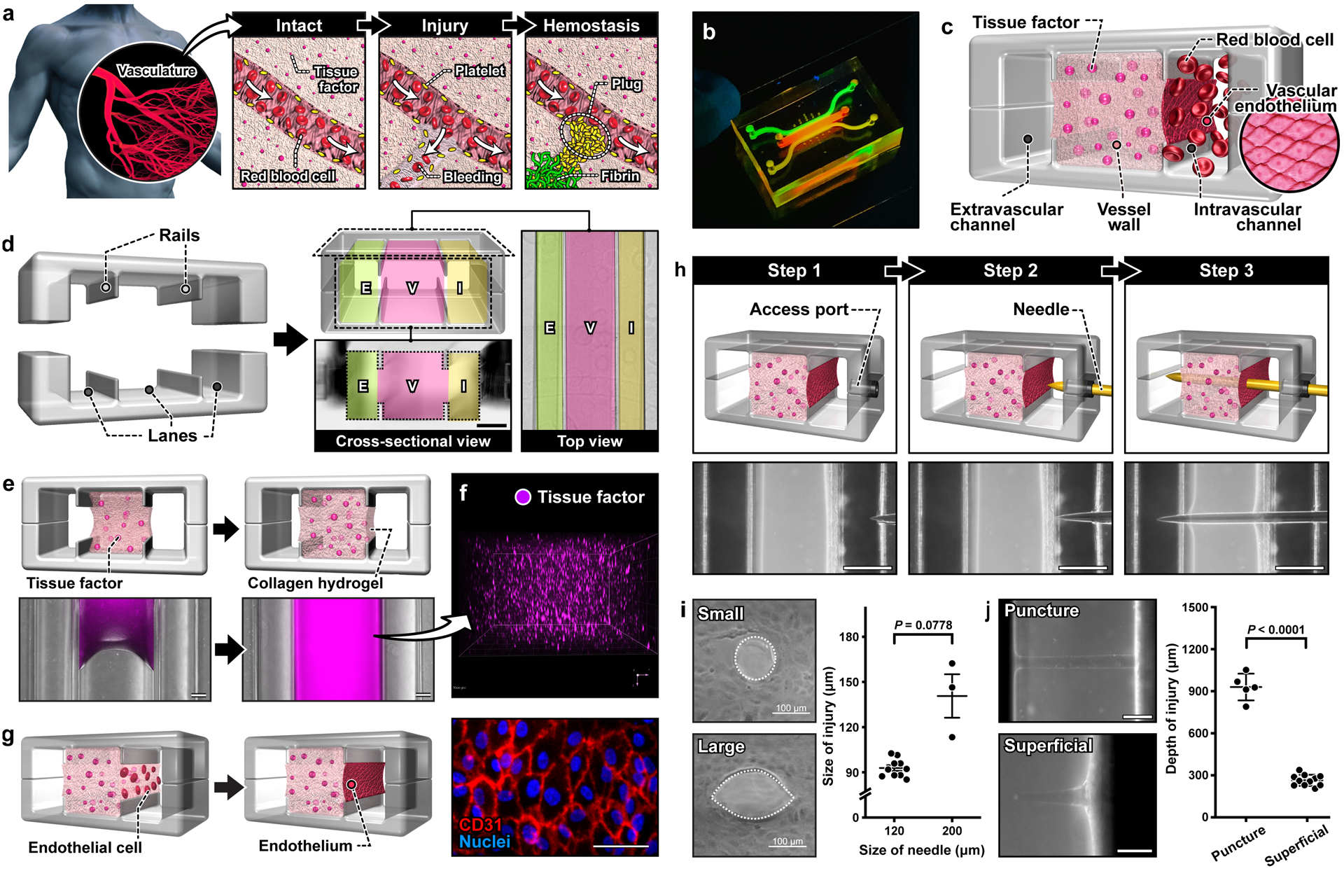
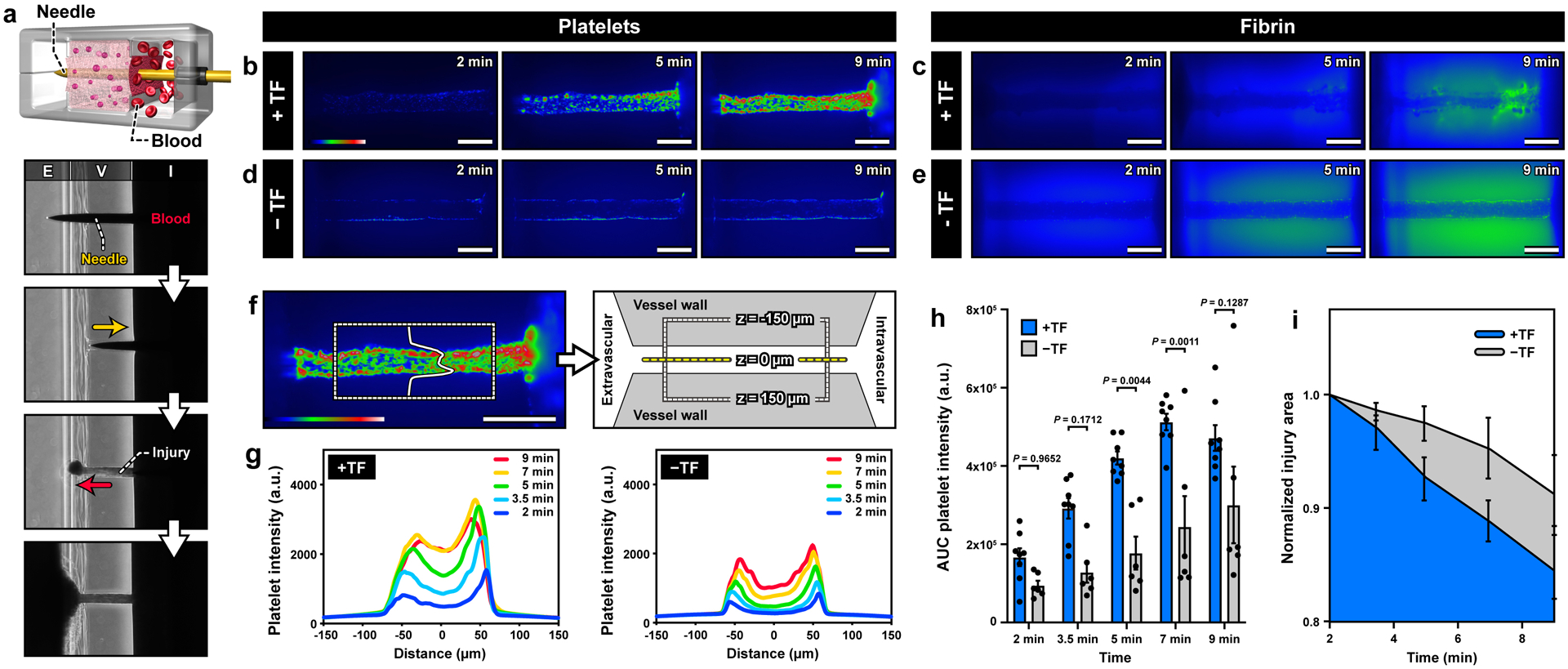
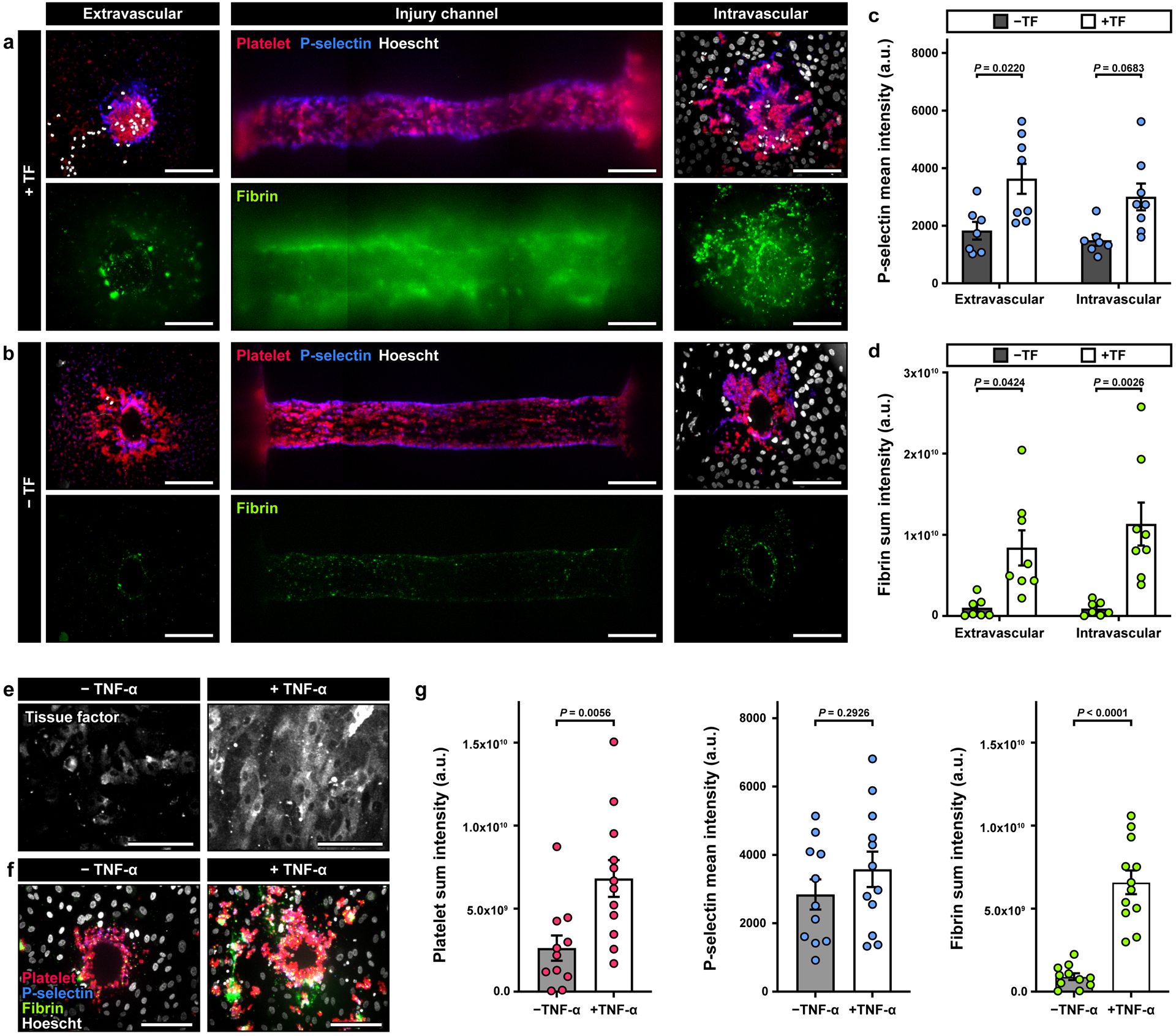
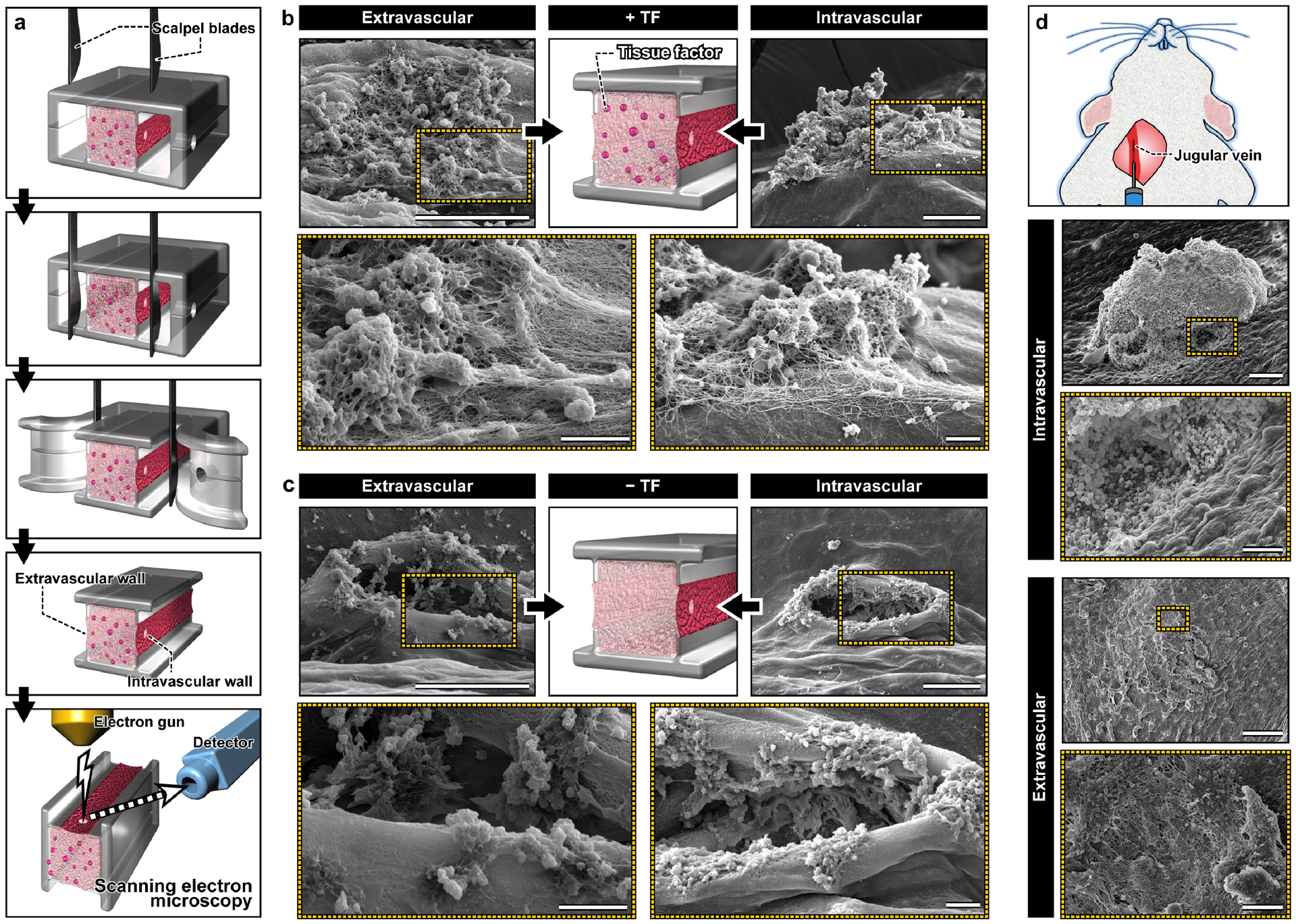
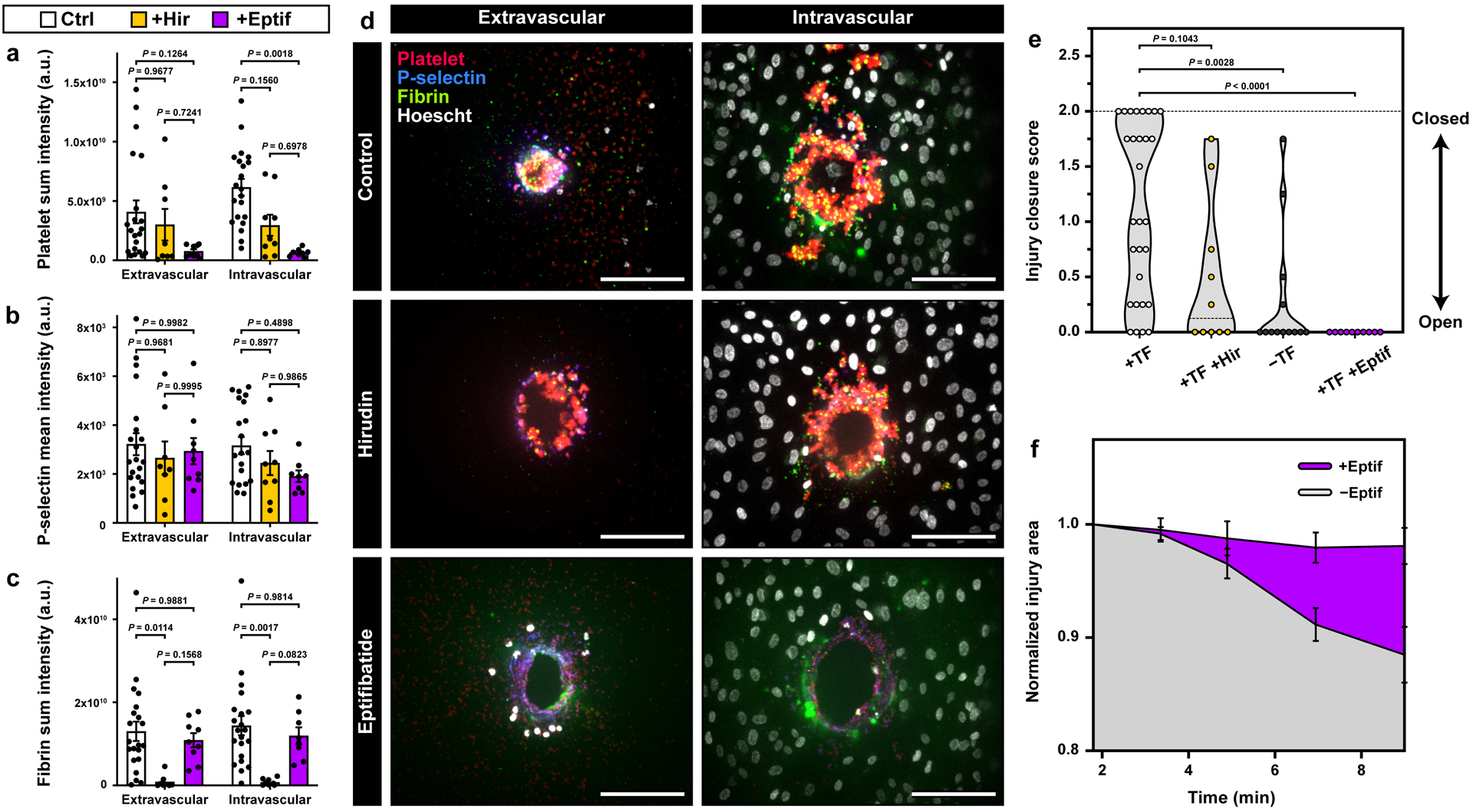
Hemostasis is an innate protective mechanism that plays a central role in maintaining the homeostasis of the vascular system during vascular injury. Studying this essential physiological process is often challenged by the difficulty of modeling and probing the complex dynamics of hemostatic responses in the native context of human blood vessels. To address this major challenge, this paper describes a microengineering approach for in vitro modeling of hemostasis. This microphysiological model replicates the living endothelium, multilayered microarchitecture, and procoagulant activity of human blood vessels, and is also equipped with a microneedle that is actuated with spatial precision to simulate penetrating vascular injuries. The system recapitulates key features of the hemostatic response to acute vascular injury as observed in vivo, including i) thrombin-driven accumulation of platelets and fibrin, ii) formation of a platelet- and fibrin-rich hemostatic plug that halts blood loss, and iii) matrix deformation driven by platelet contraction for wound closure. Moreover, the potential use of this model for drug testing applications is demonstrated by evaluating the effects of anticoagulants and antiplatelet agents that are in current clinical use. The vascular injury-on-a-chip may serve as an enabling platform for preclinical investigation of hematological disorders and emerging therapeutic approaches against them.

Keywords: fibrin; hemostasis; microphysiological system; platelets; vascular injury-on-a-chip.


Conflict of interest statement

Conflict of Interest

D.H. holds equity in Emulate Inc.

Figures

Figure 1.
Figure 1.. A human vascular injury-on-a-chip for in vitro modeling of hemostasis after a penetrating injury.
a. When an injury occurs in a blood vessel, a hemostatic plug stops bleeding. b. Image of a blood vessel-on-a-chip microdevice. c. The system is designed to model three distinct tissue compartments at the injury site. d. Microfabricated rails on the top and bottom channel walls divide the assembled microfluidic device into 3 lanes that become the intravascular (I), vessel wall (V), and extravascular (E) compartments. Scale bar, 500 μm. e. Collagen mixed with lipidated tissue factor is loaded and polymerized in the middle lane of the device. f. A 3D projection image shows the homogeneous distribution of tissue factor (stained with annexin V; magenta) in the collagen gel. g. Endothelial cells are seeded directly on top of the exposed collagen gel to form a confluent monolayer. Scale bar, 50 μm. h. Sequential steps to create an injury in the device. The micrographs show the top view of the device as an acupuncture needle is inserted through the engineered vessel wall. Scale bars, 500 μm. i. Representative images and quantification of puncture injuries that result from the insertion of 120 μm (small) and 200 μm (large) needles. j. Representative images of injuries with different penetration depths. Scale bars, 200 μm (puncture) and 100 μm (superficial). Graphs show mean ± SEM. An unpaired t-test with Welch’s correction was used for statistical analysis in i and j.
Figure 2.
Figure 2.. Formation of platelet and fibrin-rich hemostatic plugs after a puncture injury
. a. In the microdevice, bleeding is modeled as the leakage of blood through the injury due to the pressure difference between the intravascular (I) and extravascular (E) channels. Representative images of platelet deposition (b,d) and fibrin accumulation (c,e) in the presence (top row) and absence (bottom row) of tissue factor (TF). Scale bars, 200 μm. The color scale in b and d indicates the number of platelets. Green in c and e shows fluorescence emitted by anti-fibrin antibody. In the presence of TF (c), fibrin deposits are detected as aggregates with intense green fluorescence in the injury channel at 9 min. The diffuse green haze seen in the matrix, particularly in the absence of TF, is due to the absorption of the fluorescently-tagged anti-fibrin antibody into the hydrogel vessel wall. f. A region of interest in the vessel wall (shown with dotted lines) for microfluorimetric analysis of platelet deposition across the width of the injury. g. Line scan of fluorescence intensity averaged over the length of the injury channel. h. Plot of the area under the curves in g over time. i. Quantification of the change in the area of the 2D view of the injury shows greater matrix contraction over time in the presence of TF. Graphs show mean ± standard error (3 donors; +TF: 8 devices, -TF: 6 devices). Two-way ANOVA and Tukey’s multiple comparison tests were used for statistical analysis in c and d.
Figure 3.
Figure 3.. Characterization of platelet activation and fibrin formation.
a, b. Maximum projection confocal images of the injury opening on the extravascular (left) and intravascular (right) sides. The middle column shows the top-down view of the injury in the vessel wall. Red, blue, green, and white show immunostaining of platelets, P-selectin+ platelets, fibrin, and cell nuclei. Quantification of the mean fluorescence intensity (MFI) of P-selectin (c) and the sum intensity of fibrin (d) from a 40 μm-thick z-stack. The results indicate an increase in intravascular platelet activation and fibrin accumulation in the presence of TF, and an increase in fibrin at the extravascular end of the channel (3 donors; +TF: 8 devices, -TF: 6 devices). e-g. Devices were perfused overnight with buffer ± TNF-α (1 ng/ml) prior to the start of the experiment. Tissue factor was not embedded in the collagen gel. e. Confocal images show increased TF expression in endothelial cells after TNF-α treatment. f. Confocal images obtained from the intravascular side of the injury channel after blood perfusion illustrate an increase in platelet and fibrin accumulation in TNF-α-treated devices. g. Quantification of platelet and fibrin sum intensity, and P-selectin MFI, (4 donors; +TNFα: 11 devices, - TNFα: 10 devices). Data are shown as mean ± SEM. Two-way ANOVA and Tukey’s multiple comparison tests were used for the statistical analysis in c and d. Welch’s t-test was used for statistical analysis in g.
Figure 4.
Figure 4.. In vitro-in vivo comparison of hemostatic plugs using SEM.
a. Microblades are used to precisely excise the device and expose the intravascular and extravascular sides of the hemostatic plugs formed in the vascular injury-on-a-chip for morphological examination using SEM. b. In the TF-containing device, hemostatic plugs composed of platelets (spherical aggregates) and fibrin (fibrous meshwork) fill the holes in the intravascular and extravascular sides of the injury. Scale bars, 60 μm (top; lower magnification) and 10 μm (bottom: higher magnification). c. In the absence of TF, platelets adhere to the exposed collagen, but fail to fill the hole created by the injury. Scale bars, 60 μm (top; lower magnification) and 10 μm (bottom: higher magnification). d. Scanning electron micrographs obtained from a murine model of jugular vein injury show a large hemostatic plug and a dense network of platelets and fibrin at the intravascular and extravascular openings of the injury, respectively. Scale cars, 100 μm (intravascular; lower magnification) and 50 μm (intravascular; higher magnification), 300 μm (extravascular; lower magnification) and 30 μm (extravascular; higher magnification).
Figure 5.
Figure 5.. Drug testing in the vascular injury-on-a-chip.
a-c. Quantification of platelet deposition (a), platelet activation (b), and fibrin accumulation (c) in the hirudin- and Eptifibatide-treated devices (Control: 6 donors, 21 devices; Hirudin: 4 donors, 9 devices; Eptifibatide: 4 donors, 9 devices). d. Representative maximum projection confocal images of the extravascular (left) and intravascular (right) injury openings with no treatment (top), hirudin (middle), and eptifibatide (bottom). e. Violin plot of the injury channel closure scores obtained at the final time point (+TF: 8 donors, 29 devices; +Hir: 4 donors, 10 devices; -TF: 5 donors, 13 devices; +Eptif: 4 donors, 10 devices). f. Quantification of changes in normalized injury area over time as assessment of platelet-driven matrix deformation (4 donors, +Eptif: 10 devices, -Eptif: 12 devices). Graphs in a-c and f show mean ± SEM. Two-way ANOVA and Tukey’s multiple comparison tests were used for statistical analysis in a-c and f. Kruskal-Wallis and Dunn’s multiple comparison tests were used in e. The results show that in our model, eptifibatide causes reduction in platelet accumulation, platelet activation, matrix deformation, and injury channel closure. Hirudin inhibits fibrin accumulation and injury closure.

Similar articles

Cited by

References

    1. Tomaiuolo M, Brass LF and Stalker TJ, Interv Cardiol Clin 2017, 6, 1–12; - PMC - PubMed
    2. Monroe DM and Hoffman M, Arterioscler Thromb Vasc Biol 2006, 26, 41–48. - PubMed
    1. Jackson SP, Nat Med 2011, 17, 1423–1436. - PubMed
    1. Stalker TJ, Welsh JD, Tomaiuolo M, Wu J, Colace TV, Diamond SL and Brass LF, Blood 2014, 124, 1824–1831; - PMC - PubMed
    2. Tomaiuolo M, Stalker TJ, Welsh JD, Diamond SL, Sinno T and Brass LF, Blood 2014, 124, 1816–1823; - PMC - PubMed
    3. Welsh JD, Stalker TJ, Voronov R, Muthard RW, Tomaiuolo M, Diamond SL and Brass LF, Blood 2014, 124, 1808–1815. - PMC - PubMed
    1. Jagadeeswaran P, Cooley BC, Gross PL and Mackman N, Circ Res 2016, 118, 1363–1379. - PubMed
    1. Greene TK, Schiviz A, Hoellriegl W, Poncz M, Muchitsch EM, Animal S Models Subcommittee of the and I. Standardization Committee Of The, J Thromb Haemost 2010, 8, 2820–2822. - PubMed

Publication types