Review
. 2020 Oct 17;23(11):101687.
doi: 10.1016/j.isci.2020.101687. eCollection 2020 Nov 20.

Nanoarchitecting Hierarchical Mesoporous Siliceous Frameworks: A New Way Forward

Affiliations
Review

Nanoarchitecting Hierarchical Mesoporous Siliceous Frameworks: A New Way Forward

Ranjith Kumar Kankala et al. iScience. .

Abstract

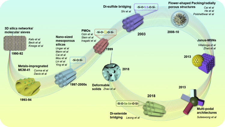
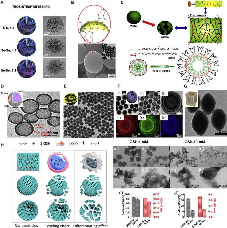
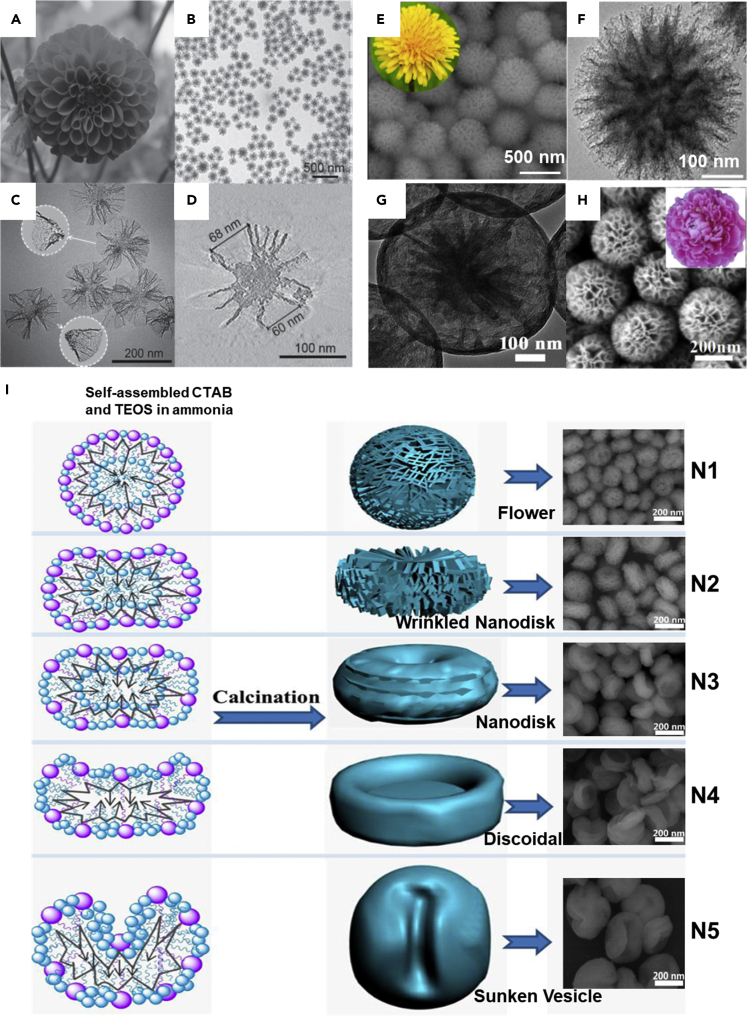
Owing to their attractive physicochemical and morphological attributes, mesoporous silica nanoparticles (MSNs) have attracted increasing attention over the past two decades for their utilization in diversified fields. Despite the success, these highly stable siliceous frameworks often suffer from several shortcomings of compatibility issues, uncontrollable degradability leading to long-term retention in vivo, and substantial unpredictable toxicity risks, as well as deprived drug encapsulation efficiency, which could limit their applicability in medicine. Along this line, various advancements have been made in re-engineering the stable siliceous frameworks, such as the incorporation of diverse molecular organic, as well as inorganic (cationic and anionic) species and monitoring the processing, as well as formulation parameters, resulting in the hetero-nanostructures of irregular-shaped (Janus and multi-podal) and dynamically-modulated (deformable solids) architectures with high morphological complexity. Insightfully, this review gives a brief emphasis on re-engineering such stable siliceous frameworks through modifying their intrinsic structural and physicochemical attributes. In conclusion, we recapitulate the review with exciting perspectives.

Keywords: Materials Science Engineering; Nanomaterials; Nanoparticles; Nanostructure.


Figures

None
Graphical abstract
Figure 1
Figure 1
Schematic Illustrating the Re-engineering of the Highly Rigid, Hierarchical Siliceous Frameworks toward the Fabrication of Diversified Molecular-Integrated, Dynamically-Modulated, and Asymmetrical-Shaped Architectures.
Figure 2
Figure 2
Schematic Illustrating the Timeline Progress of Breakthroughs in Tuning or Nanoarchitecting the Mesoporous Siliceous Frameworks.
Figure 3
Figure 3
Fabrication of Biodegradable PMOs (A) Schematic showing various organic (aliphatic and aromatic) functional groups installed in the siliceous nanoassemblies for advanced applications. (B) Schematic illustration as well as transmission electron microscope (TEM) images are showing PMO nanospheres with mixed silanes in 50/50 before (i) and after 48 hr of degradability in the physiological conditions (ii–vi). Reproduced with permission from (Croissant et al., 2014a). Copyright 2014, John Wiley and Sons. (C) Design of mixed PMO nanoparticles, composed of either bis (triethoxysilyl)ethylene, (E), or bis (triethoxysilyl)benzene (B), respectively; one-pot synthesis of AE or AB gold (Au) core-PMO shell nanoparticles, respectively, composed of either the E or B moiety; one-pot synthesis of AE2 or AB2 Au core-mixed PMO shell nanoparticles, composed of either 2PS and E (AE2) or 2PS and B (AB2 nanoparticles). Reproduced with permission from (Croissant et al., 2014b). Copyright 2014, American Chemical Society.
Figure 4
Figure 4
Disulfide/Diselenide-Bridged Organosilica Hybrid Constructs (A) Reconstructed three-dimensional (3D) models and corresponding TEM micrographs of disulfide/diselenide-bridged organosilica constructs. Reproduced with permission from (Shao et al., 2018). Copyright 2018, John Wiley & Sons. (B) Schematic showing the arrangement of disulfide bridging over the solid MSNs. Reproduced with permission from (Kim et al., 2012). Copyright 2012, American Chemical Society. (C) Schematic representation for the CTAC-based molecularly organic-inorganic hybrid composition of thioether-bridged mesoporous organosilicas. Reproduced with permission from (Wu et al., 2015). Copyright 2015, John Wiley & Sons. (D) Electron microscopy image of hybrid PLGA@organosilica nanoparticles. Reproduced with permission from (Quesada et al., 2013). Copyright 2013, American Chemical Society. (E) TEM image of the yolk-shell mesoporous nanoparticles with thioether-bridged organosilica frameworks prepared by hydrothermal treatment. Reproduced with permission from (Teng et al., 2014). Copyright 2014, American Chemical Society. (F) (i–iii) Triple-shelled PMO hollow spheres with ordered radial mesochannels prepared by a one-step hydrothermal treatment of the organosilica spheres with different growth cycles (iv-vi) and their corresponding EDX elemental mapping images. Reproduced with permission from (Teng et al., 2015). Copyright 2015, American Chemical Society. (G) TEM image of Prussian blue-based core-shell thioether-bridged organosilica architectures. Reproduced with permission from (Tian et al., 2017). Copyright 2017, John Wiley & Sons. (H) Schematic showing the pore structure-dependent degradability of nanoparticles within healthy and cancer cells. Degradation test of degradable dendritic mesoporous organosilica nanoparticles (DDMONs) (a1-a4) and mesoporous organosilica nanoparticles MONs (b1-b4) tested at 1 and 10 mM GSH solution in the presence of serum and (c and d) their corresponding enumerated outcomes. GSH oxidation percentage (black columns) and relative quantity of –SH groups after incubation of DDMONs or MONs in GSH solution in the presence of serum. Reproduced with permission from (Yang et al., 2016b). Copyright 2016, American Chemical Society.
Figure 5
Figure 5
Metallic Linkers in the Siliceous Frameworks for Diverse Biomedical Applications (A) Schematic illustration showing the synthesis of designed hierarchical metal-impregnated MSNs elucidating the mechanistic illustration of pH-responsive delivery of a drug in the tumor environment. Reproduced with permission from (Kankala et al., 2017). Copyright 2017, American Chemical Society. (B) Illustration showing the fabrication of various metal-doped MSNs along with the structures elucidating the arrangement of transition metals in the silica wall and their corresponding optical sample images, as well as TEM micrographs. (C) pH-responsive release of doxorubicin (Dox) from Cu-Fe-MSNs in vitro at various time intervals in the simulated fluids, compared to naked MSNs. (D) Cellular internalization illustrating the lysosomal escape of free Dox and Cu-Fe-MSN-Dox in HeLa cells and their respective RGB fluorescence intensity profiles of DAPI, LysoTracker, and Dox at the selected region (yellow line) from the samples, (I) Free Dox, and (ii) Cu-Fe-MSN-Dox, respectively. (E) Confocal laser scanning microscope (CLSM) images are showing the ROS levels correlating to 2′,7′-dichlorofluorescein diacetate (DCF-DA) fluorescence in HeLa cells after treatment with bare MSNs, Cu-MSNs, Fe-MSNs, Cu-Fe-MSNs, and Cu-Fe-MSN-Dox. (F) Degradation of Cu-Fe-MSNs in vitro in (i) media with 10% serum and phosphate-buffered saline (PBS), (ii) pH-7.4, and (iii) pH-5.0. (the inset box showing the optical images of samples after centrifugation on left and dispersion, of the respective sample on right) (iv) Hydrodynamic sizes of Cu-Fe-MSNs in 10% serum-containing media and PBS. Reproduced with permission from (Liu et al., 2019). Copyright 2019, Elsevier. (v) TEM images of Fe-HMSNs after the biodegradation in serum. Reproduced with permission from (Wang et al., 2017). Copyright 2017, John Wiley and Sons.
Figure 6
Figure 6
Janus-Type Nanoconstructs for Advanced Biomedical Applications (A) Dual compartment Janus MSNs, UCNP@Si O 2@ mSi O 2&PMOs by the anisotropic island nucleation and growth method (UCNP = NaGdF4:Yb,Tm@NaGdF4, mSi O 2 = mesoporous silica shell) and their corresponding TEM images. Reproduced with permission from (Li et al., 2014). Copyright 2014, American Chemical Society. (B) Characterization of Janus MSNs with different sizes coated with Pt (2 nm) by electron beam deposition. (C) High-angle annular dark-field–scanning TEM (HAADF-STEM) image and element mapping of Janus MSNs. Reproduced with permission from (Ma et al., 2015). Copyright 2015, American Chemical Society. Note: Further permissions related to the material excerpted should be directed to the American Chemical Society. (D) Schematic illustration of Au nanoparticle-coated Janus MSNs by vacuum sputtering. Reproduced with permission from (Xuan et al., 2016). Copyright 2016, American Chemical Society. (E) Schematic showing the fabrication procedure for the Dox-loaded Ag-MSNs and their application towards SERS imaging and pH-sensitive drug delivery in cancer therapy. Reproduced with permission from (Shao et al., 2016). Copyright 2016, American Chemical Society. (F) Schematic showing the synthetic procedure for the Janus magnetic mesoporous organosilica nanoparticles and their application for combined PDT and magnetic hyperthermia. TEM images of constructs showing the selective degradability behavior in 5 × 10−3 m GSH solution for 1 and 5 d. Reproduced with permission from (Wang et al., 2019c). Copyright 2019, John Wiley & Sons. (G) (i) Schematic illustrating the synthesis of Janus MSNs and their advantages in hemocompatibility and maturation of immune cells. (ii-vi) TEM images (A−E) of Janus MSNs 1.25-t-60 collected at different reaction times (t = 2, 3, 6, 9, and 24 hr, respectively). (vii) Variation of tail length (black bar) and head coverage (gray bar) as a function of t. Bars represent the mean ± SEM (n = 20). Reproduced with permission from (Abbaraju et al., 2017). Copyright 2017, American Chemical Society.
Figure 7
Figure 7
Multi-Podal Architectures (A) Influence of the 1,4-bis (triethoxysilyl)benzene precursor concentration on the size and morphology of PMO materials, as displayed by TEM micrographs. Reproduced with permission from (Croissant et al., 2016a). Copyright 2016, John Wiley & sons. (B) TEM images (i-iv) of BE mp-PMO containing one to several pods and corresponding depicted schematic nanoparticle representations and high-resolution scanning transmission electron microscopy (HR-STEM) images. The red hexagons highlight the morphology of the E-PMO pods. Scale bars represent 100 nm. Reproduced with permission from (Croissant et al., 2015a). Copyright 2015, John Wiley & sons. (C) Synthesis and characterization of Tribulus-like tetrapod nanocomposites. (i) Schematic showing the fabrication process of the tetrapods Fe3 O 4@Si O 2@RF&PMOs nanoparticles based on the surface kinetics-mediated multi-site nucleation strategy. (ii, iii) TEM images at different magnifications, (iv) scanning electron microscope (SEM) image, and (v) element mapping of the Tribulus-like tetrapods Fe3 O 4@Si O 2@RF&PMOs mesoporous nanocomposites. Inset in (ii): a digital photo of Tribulus seeds. Inset in (iii): a 3D structural model of the tetrapods Fe3 O 4@Si O 2@RF&PMOs nanoparticles. Reproduced with permission from (Zhao et al., 2019). Copyright 2019, Nature publishing group.
Figure 8
Figure 8
Flower-Shaped Packing of Siliceous Architectures (A–D) (A) A picture of a dahlia photographed by (C) Xu at Tasmania. TEM images at (B) low magnification, (C) high magnification, and (D) an ET slice of MSNs. Reproduced with permission from (Xu et al., 2015). Copyright 2015, John Wiley & sons. (E and F) (E) SEM and (F) TEM micrographs of Si O 2 nanoflowers containing elongated spikes, which assembled in a divergent way to form hierarchical dandelion flower-like morphology as shown in the inset of figure E. Reproduced with permission from (Das et al., 2019). Copyright 2019, Elsevier. (G) TEM images of flower-shaped yolk-shell Si O 2 nanospheres. Reproduced with permission from (Zheng et al., 2018). Copyright 2018, Elsevier. (H) SEM image of the individual core-shell magnetic organosilica-based nanoflowers with radial wrinkles. Reproduced with permission from (Gao et al., 2017). Copyright 2017, Elsevier. (I) Illustration representing the synthetic procedure of MSNs with different morphologies. Reproduced with permission from (Chen et al., 2018). Copyright 2018, American Chemical Society.
Figure 9
Figure 9
Dynamically Modulated Siliceous Nanoarchitectures (A–C) (A) TEM images of (a) thioether-, (b) benzene-, and (c) ethane-bridged mesostructured organosilica nanospheres synthesized via a CTAB directed sol-gel process. TEM images of (a1, a2) thioether-, (b1, b2) benzene-, and (c1, c2) ethane-bridged HPMO nanocapsules prepared by etching the corresponding organosilica nanospheres in a mild NaOH solution. Insets in (a2, b2, and c2) are the structural models of the deformed HPMO nanocapsules. (B) Illustration of the formation mechanism of the deformable HPMO nanocapsules. (C) TEM images of the thioether-bridged mesostructured organosilica spheres incubated in NaOH aqueous solution (0.48 M) for (a) 1, (b) 3, (c and d) 5, and (e) 20 min, as well as (f) 1 hr. The arrow in (b) indicates the voids. Scale bars represent 50 nm. Reproduced with permission from (Teng et al., 2018). Copyright 2018, American Chemical Society. (D) Synthesis and characterization of silica rings. (a) Chemical structures. (b) Molecular graphic of the formation of silica rings. (c) A molecular graphic of the worm-like 1D assembly of silica rings. (d) Illustration of micelle surface wrapping around a silica cluster preventing attachment to other micelles (transparent top) due to the strong electrostatic repulsion. (e) Different structures of silica ring with more complex geometries, including rings with one additional arm (top row) and tetrahedral cages (bottom row). Scale bar in the insets: 10 nm. 1D, 2D, and 3D ring assemblies facilitated by PEGs. (f) Cryo-EM image of elongated and segmented 1D ring assemblies obtained upon PEG addition and their substantial transformation to (g) 2D hierarchical arrays of silica rings and (h) 3D assemblies. Reproduced with permission from (Ma et al., 2018). Copyright 2018, American Chemical Society.

Similar articles

Cited by

References

    1. Abbaraju P.L., Meka A.K., Song H., Yang Y., Jambhrunkar M., Zhang J., Xu C., Yu M., Yu C. Asymmetric silica nanoparticles with tunable head–tail structures enhance hemocompatibility and maturation of immune cells. J. Am. Chem. Soc. 2017;139:6321–6328. - PubMed
    1. An N., Lin H., Yang C., Zhang T., Tong R., Chen Y., Qu F. Gated magnetic mesoporous silica nanoparticles for intracellular enzyme-triggered drug delivery. Mater. Sci. Eng. C. 2016;69:292–300. - PubMed
    1. Argyo C., Weiss V., Bräuchle C., Bein T. Multifunctional mesoporous silica nanoparticles as a universal platform for drug delivery. Chem. Mater. 2014;26:435–451.
    1. Asefa T., MacLachlan M.J., Coombs N., Ozin G.A. Periodic mesoporous organosilicas with organic groups inside the channel walls. Nature. 1999;402:867–871.
    1. Aspromonte S.G., Sastre Á., Boix A.V., Cocero M.J., Alonso E. Cobalt oxide nanoparticles on mesoporous MCM-41 and Al-MCM-41 by supercritical CO2 deposition. Microporous Mesoporous Mater. 2012;148:53–61.

LinkOut - more resources