. 2020 Nov 6;12(11):2607.
doi: 10.3390/polym12112607.

Multi-Scale Digital Image Correlation Analysis of In Situ Deformation of Open-Cell Porous Ultra-High Molecular Weight Polyethylene Foam

Affiliations

Multi-Scale Digital Image Correlation Analysis of In Situ Deformation of Open-Cell Porous Ultra-High Molecular Weight Polyethylene Foam

Eugene S Statnik et al. Polymers (Basel). .

Abstract

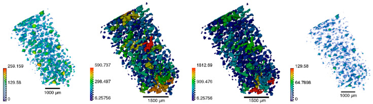
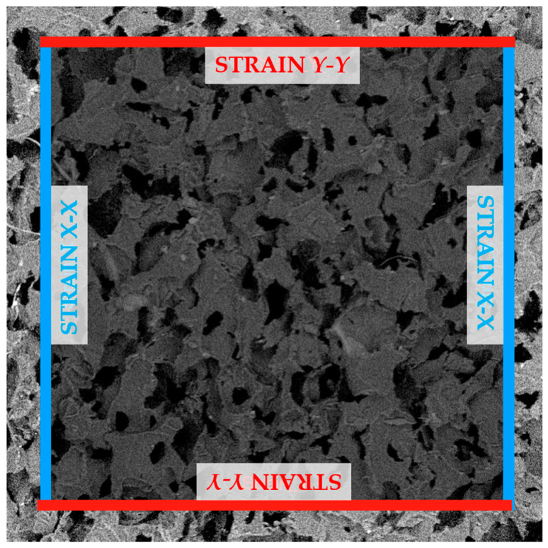
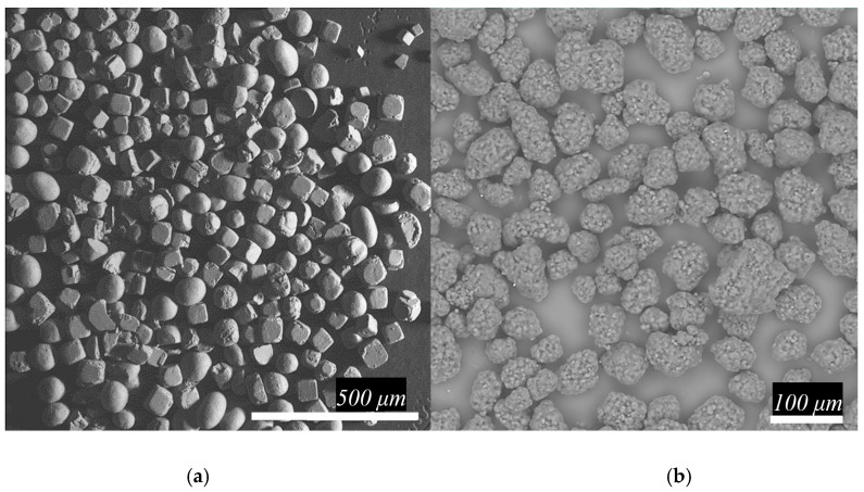
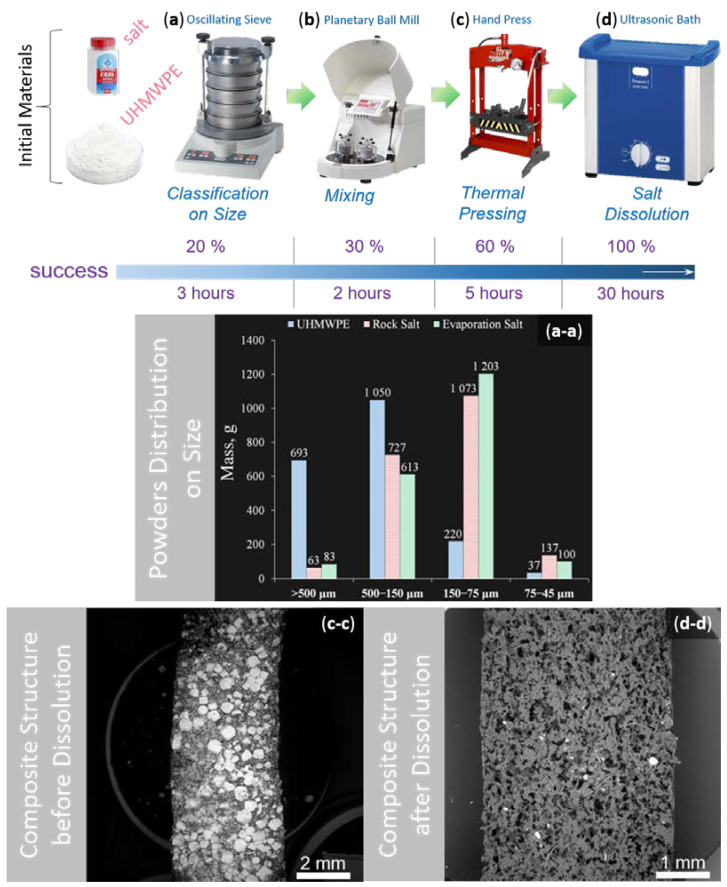
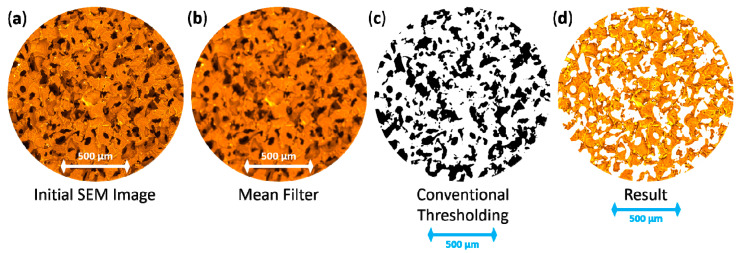
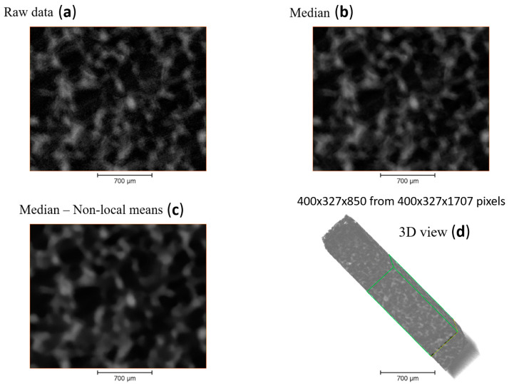
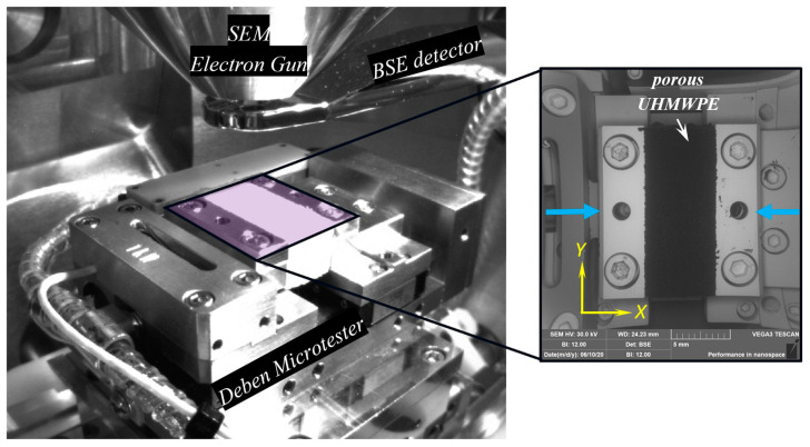
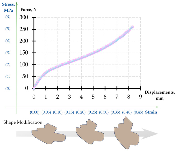
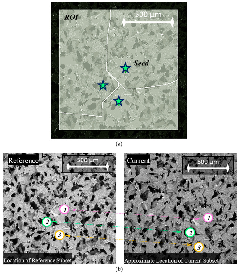
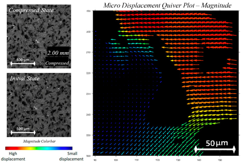
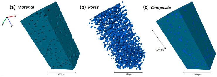
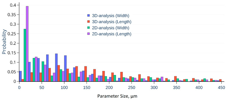
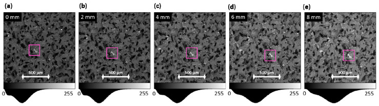
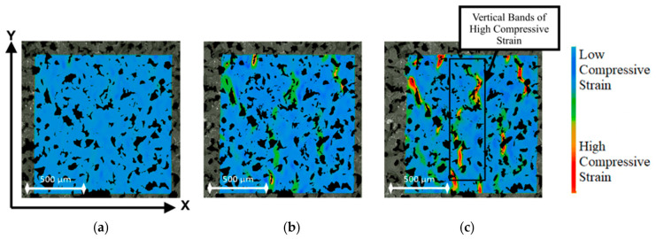
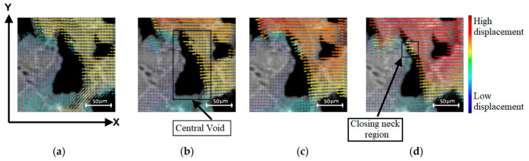
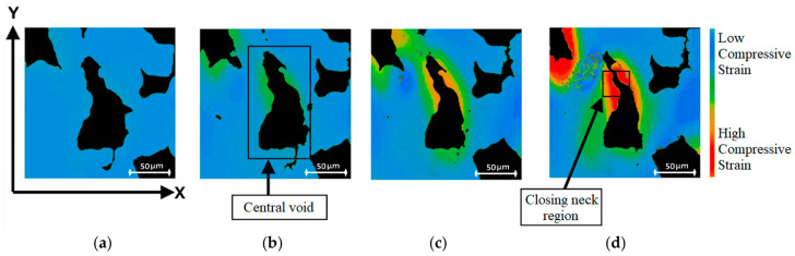
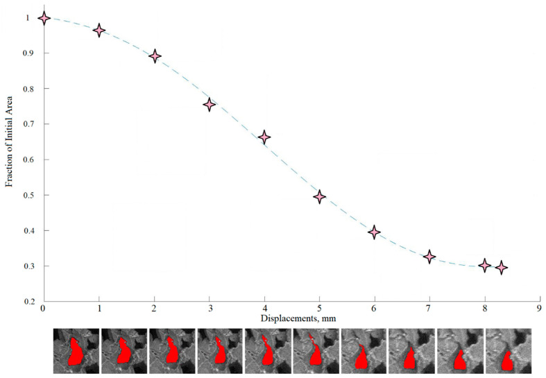
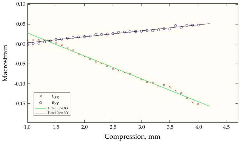
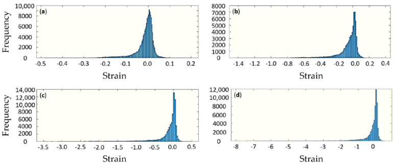
Porous ultra-high molecular weight polyethylene (UHMWPE) is a high-performance bioinert polymer used in cranio-facial reconstructive surgery in procedures where relatively low mechanical stresses arise. As an alternative to much stiffer and more costly polyether-ether-ketone (PEEK) polymer, UHMWPE is finding further wide applications in hierarchically structured hybrids for advanced implants mimicking cartilage, cortical and trabecular bone tissues within a single component. The mechanical behaviour of open-cell UHMWPE sponges obtained through sacrificial desalination of hot compression-moulded UHMWPE-NaCl powder mixtures shows a complex dependence on the fabrication parameters and microstructural features. In particular, similarly to other porous media, it displays significant inhomogeneity of strain that readily localises within deformation bands that govern the overall response. In this article, we report advances in the development of accurate experimental techniques for operando studies of the structure-performance relationship applied to the porous UHMWPE medium with pore sizes of about 250 µm that are most well-suited for live cell proliferation and fast vascularization of implants. Samples of UHMWPE sponges were subjected to in situ compression using a micromechanical testing device within Scanning Electron Microscope (SEM) chamber, allowing the acquisition of high-resolution image sequences for Digital Image Correlation (DIC) analysis. Special masking and image processing algorithms were developed and applied to reveal the evolution of pore size and aspect ratio. Key structural evolution and deformation localisation phenomena were identified at both macro- and micro-structural levels in the elastic and plastic regimes. The motion of pore walls was quantitatively described, and the presence and influence of strain localisation zones were revealed and analysed using DIC technique.

Keywords: Avizo; Deben Microtest; Ncorr; SEM-DIC; porous UHMWPE; tomography.


Conflict of interest statement

The authors declare no conflict of interest.

Figures

Figure A1
Figure A1
Avizo post-processing of X-Ray Tomography data of porous UHMWPE: pore thickness, width, length, and distance.
Figure A2
Figure A2
Bands of values used to calculate DIC macrostrain from displacement values in those selected matrix rows/columns. Strain in X was calculated from the difference between average blue band values divided width, and strain in Y was calculated similarly using the red bands and the height.
Figure 1
Figure 1
The microphotograph of the used powders: (a) table salt and (b) UHMWPE.
Figure 2
Figure 2
The methodological process for porous sample preparation based on UHMWPE: (a) UHMWPE and salt powders classification on size and obtained particles size distributions (a-a); (b) Mixing of extracting powders in the necessary proportion; (c) Thermal pressing of achieved mixture and observed composite structure (c-c); (d) Desalination process and achieved polymer porous structure (d-d).
Figure 3
Figure 3
The sequence of SEM image processing (with use of false colour) from raw to segmented data:.(a) Initial SEM image of porous structure;.(b) Image after mean filter; (c) Binary image after traditional thresholding approach; (d) Masked initial image.
Figure 4
Figure 4
Pre-processing of the obtained 3D dataset: (a) raw data; (b) data after median filter; (c) data after denoising; and (d) 3D view of the entire dataset with selected green bounds of the region of interest.
Figure 5
Figure 5
The view field of an experimental setup in SEM.
Figure 6
Figure 6
The nominal stress–strain curve obtained from the Deben Microtest for porous UHMWPE.
Figure 7
Figure 7
Seed placement on porous sample images captured by SEM: (a) clear view of seed regions; (b) change in position of seeds from initial to final images.
Figure 8
Figure 8
Graphical output from the custom quiver plot code showing magnitude vectors for a select void region, with magnitude and colour corresponding to the rectangular colour bar.
Figure 9
Figure 9
The 3D view of different composite components, namely, (a) porous material; (b) only pores; and (c) material with selected pores.
Figure 10
Figure 10
The distribution of pore length and width for 2D and 3D case.
Figure 11
Figure 11
Movement of structural characteristics during compression with plotted intensity distribution histogram below for (a) 0 mm; (b) 2 mm; (c) 4 mm; (d) 6 mm; and (e) 8 mm compression steps, respectively.
Figure 12
Figure 12
Ncorr strain maps with colour bar for (a) 1 mm, (b) 2 mm, and (c) 3 mm compression.
Figure 13
Figure 13
Quiver plot with colour bar showing void compression for (a) 1 mm, (b) 2 mm, (c) 3 mm, and (d) 4 mm compression.
Figure 14
Figure 14
Strain map with colour bar from Ncorr showing strain development for a central void, as seen at (a) 1 mm, (b) 2 mm, (c) 3 mm, and (d) 4 mm compression.
Figure 15
Figure 15
Area progression graph showing qualitative values for the area of a central void during compression.
Figure 16
Figure 16
Plot of DIC obtained strain values against compression for analysis and Poisson’s ratio calculation.
Figure 17
Figure 17
Strain distribution for different steps of compression, namely, nominal displacements: (a) 1 mm, (b) 2 mm, (c) 4 mm, and (d) 8 mm, respectively.

References

    1. Scopus Database [Electronic Resource] [(accessed on 1 September 2020)]; Available online: www.scopus.com.
    1. Zherebtsov D., Chukov D., Statnik E.S., Torokhov V. Hybrid self-reinforced composite materials based on ultra-high molecular weight polyethylene. Materials. 2020;13:1739. - PMC - PubMed
    1. Zherebtsov D., Chukov D., Torokhov V., Statnik E.S. Manufacturing of single-polymer composite materials based on ultra-high molecular weight polyethylene fibers by hot compaction. J. Mater. Eng. Perform. 2020;29:1522–1527.
    1. Maksimkin A.V., Senatov F.S., Niaza K., Dayyoub T., Kaloshkin S.D. Ultra-high molecular weight polyethylene/titanium-hybrid implant for bone-defect replacement. Materials. 2020;13:3010. doi: 10.3390/ma13133010. - DOI - PMC - PubMed
    1. Senatov F., Chubrik A., Maksimkin A., Kolesnikov E., Salimon A.I. Comparative analysis of structure and mechanical properties of porous PEEK and UHMWPE biomimetic scaffolds. Mater. Lett. 2018;239:63–66. doi: 10.1016/j.matlet.2018.12.055. - DOI