Fate and propagation of endogenously formed Tau aggregates in neuronal cells
- PMID: 33179866
- PMCID: PMC7721367
- DOI: 10.15252/emmm.202012025
Fate and propagation of endogenously formed Tau aggregates in neuronal cells
Abstract
Tau accumulation in the form of neurofibrillary tangles in the brain is a hallmark of tauopathies such as Alzheimer's disease (AD). Tau aggregates accumulate in brain regions in a defined spatiotemporal pattern and may induce the aggregation of native Tau in a prion-like manner. However, the underlying mechanisms of cell-to-cell spreading of Tau pathology are unknown and could involve encapsulation within exosomes, trans-synaptic passage, and tunneling nanotubes (TNTs). We have established a neuronal cell model to monitor both internalization of externally added fibrils, synthetic (K18) or Tau from AD brain extracts, and real-time conversion of microtubule-binding domain of Tau fused to a fluorescent marker into aggregates. We found that these endogenously formed deposits colabel with ubiquitin and p62 but are not recruited to macroautophagosomes, eventually escaping clearance. Furthermore, endogenous K18-seeded Tau aggregates spread to neighboring cells where they seed new deposits. Transfer of Tau aggregates depends on direct cell contact, and they are found inside TNTs connecting neuronal cells. We further demonstrate that contact-dependent transfer occurs in primary neurons and between neurons and astrocytes in organotypic cultures.
Keywords: Intercellular spreading; Tau aggregates; autophagy; prion-like seeding; tunneling nanotubes.
© 2020 The Authors.
Conflict of interest statement
The authors declare that they have no conflict of interest.
Figures
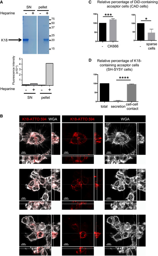
Quality control of K18 fibrils. After incubation in the presence (+) or absence (−) of heparin, fibrils were purified by ultracentrifugation. Supernatant (SN) and pellet were controlled by SDS–PAGE (18%) followed by Coomassie staining (upper panel), and by thioflavin T assay (graph below) where fluorescence intensity was monitored (Ex 450, Em 510 nm, integration time 200 ms). On the right side of the gel are the apparent molecular weights (kDa), and the white lane indicates that intervening lanes from the same gel have been spliced out. This experiment is representative of three independent preparations of fibrils.
Uptake of K18 fibrils by cells. Three representative confocal pictures (one Z‐stack in the 2D picture, orthogonal views covering 17 μm in 17 stacks) of CAD cells, first challenged with K18‐ATTO 594 fibrils, trypsinized 24 h later, and replated for an additional 24 h, in the conditions used for all coculture experiments. White is WGA staining, and red is the fibrils; scale bars are 10 μm.
Transfer of DiD in CAD cells. Left, quantification by flow cytometry of the relative percentage of DiD‐loaded acceptor cells upon treatment with CK666 during the coculture. Data represent the means (+ SD), normalized to non‐treated coculture arbitrarily set at 100%, of three independent experiments, with statistical analysis by two‐tailed unpaired t‐test (mean + CK666=120%, ***P = 0.0008). Right is the same analysis when the cell were cultured in sparse conditions, not favoring direct cell contacts (mean = 45%, three independent experiments, *P = 0.011).
Spreading of K18‐ATTO 594 fibrils in SH‐SY5Y cells. Quantification by flow cytometry of the percentage of K18‐ATTO 594‐positive acceptor cells after coculture of donor and acceptor cells (total), or culture of acceptor cells with donor‐conditioned medium for 24 h (secretion). The total transfer was arbitrarily set at 100%, and cell‐to‐cell contact transfer was calculated by subtracting secretion transfer from total transfer. Data represent the means (+ SD) of four experiments, with statistical analysis by two‐tailed unpaired t‐test (****P = 7.17E−10).
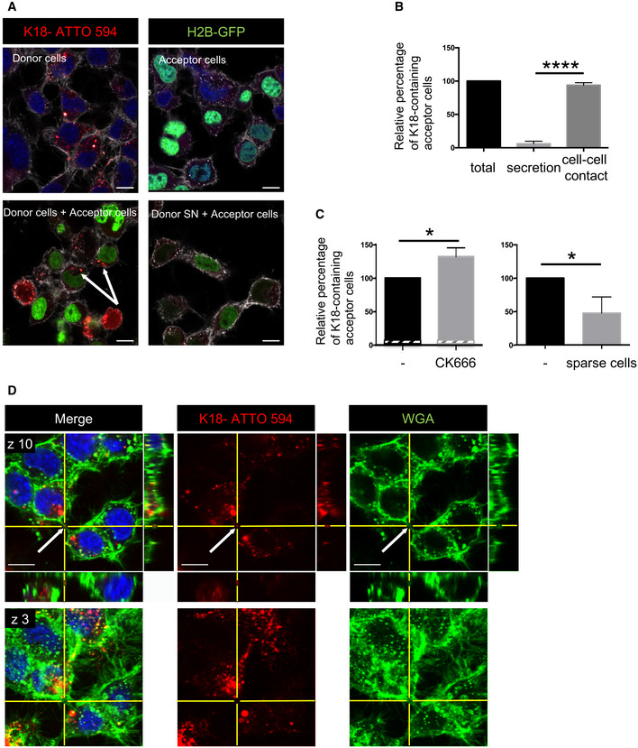
Transfer of K18‐ATTO 594 fibrils from donor cells to H2B‐GFP‐expressing acceptor cells. Representative confocal images of each population are in the upper panels, and below are pictures after 24 h of coculture of the two populations (left) and of acceptor cells treated with conditioned medium from donor cells for 24 h (SN, right). In white is the cell membrane labeling with WGA (wheat germ agglutinin) coupled to Alexa 647. The arrows point to acceptor cells containing fibrils, scale bars are 10 μm.
Quantification by flow cytometry of the percentage of K18‐ATTO 594‐positive acceptor cells after coculturing donor and acceptor cells (total), or culturing acceptor cells with donor‐conditioned medium for 24 h (secretion). The total transfer is arbitrarily set at 100%, and cell‐to‐cell contact transfer is calculated by subtracting secretion transfer from total transfer. Data represent the means (+ SD) of four independent experiments, with statistical analysis by two‐tailed unpaired t‐test (****P = 4.64E‐08).
Quantification by flow cytometry of the relative percentage of K18‐ATTO 594‐positive acceptor cells upon treatment with CK666 during the coculture. Left, data represent the means (132%) + SD, normalized to non‐treated coculture arbitrarily set at 100%, of three independent experiments, with statistical analysis by two‐tailed unpaired t‐test (*P = 0.015). The hatched area of each bar represents the part due to secretion (respectively, 4.8 and 4.3% in the absence and presence of CK666). Right is the same analysis when the cells were cultured in sparse conditions, not allowing cell‐to‐cell contacts (mean = 47.7%, three independent experiments, *P = 0.020).
Representative confocal images (40×) of CAD cells treated with 1 µM K18‐ATTO 594 fibrils, 24 h after fibril addition, and fixed and stained with WGA‐Alexa 488 (green) and DAPI (blue in the merge panels). Bottom panels are a bottom slice corresponding to the substrate‐attached surface of cells (z3), upper panels correspond to slice 10 of the same picture (z10), not attached to the substrate. On the right and below z10 pictures are the orthogonal views (xz and yz) of the same region covering 27 slices over 11 μm in total. The arrows point to red fibrils into a WGA‐positive TNT. Scale bars are 10 μm.
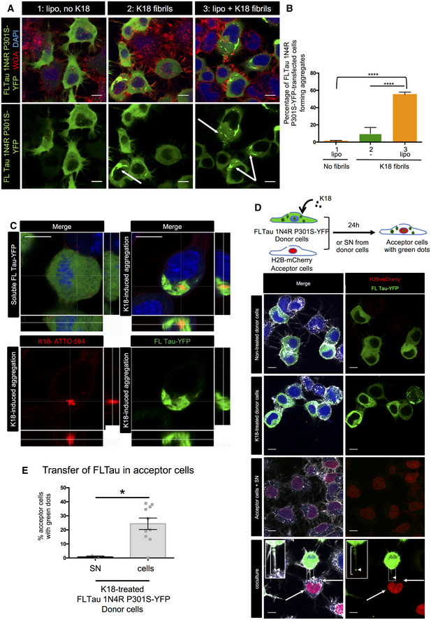
CAD cells were transfected with FL Tau 1N4R P301S‐YFP encoding plasmid for 6 h, and then challenged or not with non‐labeled K18 fibrils (sonicated, with or without Lipofectamine 2000 as indicated) and left o/n before trypsinization and replating for an additional 24 h. Cells were finally fixed, labeled with WGA, and analyzed by confocal microscopy (40× magnification). Pictures of cells containing aggregates are shown for conditions 2 and 3, representative of the results. The arrows point to cells containing fibrils; scale bars are 10 μm.
The plot shows the percentage with SEM of transfected cells where FL Tau appeared as inclusions (1, 9.8, and 55, respectively, for conditions 1, 2, and 3). Statistically significant differences are compared to the control conditions (1, Lipofectamine without fibrils) by one‐way ANOVA and Tukey's post hoc test (****P = 1.07E‐08 for 1 vs 3, 3.65E−10 for 2 vs 3). The efficiency of transfection was 47%, and the numbers of cells containing green aggregates counted were 222, 693, and 526, respectively, for conditions 1, 2, and 3, over three independent experiments.
Representative confocal pictures (63× with 1.6 zoom, one Z‐stack in the 2D picture, orthogonal views covering 5.6 μm in 17 stacks) of CAD cells treated with K18‐ATTO 594 fibrils as in (A). Upper left panel is a cell without red or green aggregates, and the three other panels are a cell where FL Tau‐YFP is aggregated. Green is FL Tau‐YFP, and red is the fibrils; scale bars are 10 μm.
Below the schematics of the experiment are representative confocal images (40× objective) of donor CAD cells (transfected with FL Tau 1N4R P301S‐YFP expression vector), challenged or not with non‐labeled K18 fibrils (respectively, second and first lane panels), acceptor cells with conditioned medium from K18‐challenged donor cells (acceptor cells + SN, third lane panels), and coculture of donor (with K18) and acceptor cells in the bottom panels. The images are representative Z‐stacks, except from the bottom panel which is a maximal projection covering five upper stacks (1.4 μm in total, allowing to visualize TNTs, not attached to the dish). In the merged images, white is WGA, green is YFP, red is mCherry, and nuclei are stained in blue. Arrows point to FLTau puncta inside acceptor cells and the arrowhead shows a green dot inside a TNT, which is indicated with a bracket. Insets are threefold enlargements of the boxed regions in the lower panels. Scale bars are 10 μm.
Quantification of the percentage of FLTau‐positive acceptor cells after coculturing donor and acceptor cells (cells), or culturing acceptor cells with donor‐conditioned medium for 24 h (SN). In the scatter dot plot, each symbol is a tile of four fields of acquisition, and bars are means (0.72 and 24.3 respectively) ± SEM. The total number of acceptor cells counted over two independent experiments was 229 for SN and 286 for cell coculture. Statistical analysis was unpaired t‐test, P = 0.0107 (*).
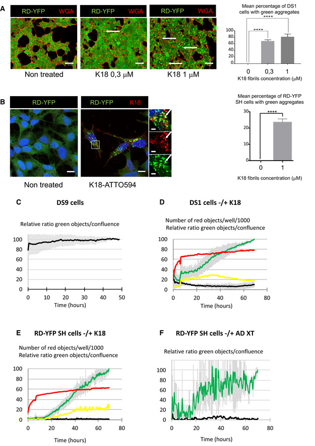
Representative confocal images of DS1 cells (expressing soluble Tau RD‐YFP), non‐treated and treated with increasing concentrations of non‐labeled K18 fibrils, fixed after 2 days, and stained with WGA‐Alexa 594 (red). The arrows point to examples of aggregate‐containing cells; scale bars are 40 μm. On the right is the quantification of the mean percentage + SEM of cells where green aggregates were detected (the total number of cells analyzed over three independent experiments was 1,188 for non‐treated, 1,552 for 0.3 μM, and 1,506 for 1 μM), with statistical analysis by one‐way ANOVA and Bonferroni's post hoc test (****P = 6.20E−06 and 6.74E−05 for 0–0.3 and 0–1 comparisons, respectively).
Representative confocal images (40×) of RD‐YFP SH cells, non‐treated and treated with 1 μM K18‐ATTO 594 fibrils, 48 h after fibril addition. Right insets are threefold enlargements of the boxed region of treated cells, merge and single‐channel pictures; white arrows point to partial colocalization. Scale bars are 10, 2 μm in the insets. On the right is the quantification of the mean percentage (24%) + SD of cells where green aggregates were detected (2,874 treated cells analyzed over six independent experiments), with statistical analysis by two‐tailed unpaired t‐test (****P = 3.75E‐07).
Relative proportion of DS9 cells expressing aggregates of Tau RD‐YFP over a 50‐h period monitored by IncuCyte. DS9 cells were left untreated, and the graph represents means of three independent experiments ± SD. See also Movie EV1.
Monitoring the conversion of DS1 cells into inclusion‐containing cells over a 70‐h period upon treatment with K18 fibrils. Cells were plated, treated or not with K18‐ATTO 594 fibrils at 1 μM (time 0), and placed into the IncuCyte incubator for 6 h and next kept in culture for an additional 60 h after medium change. The scatter plot represents means of five independent experiments (± SD for green and black curves). See also Movie EV2.
Monitoring the conversion of RD‐YFP‐expressing SH‐SY5Y cells into inclusion‐containing cells over a 70‐h period upon treatment with K18 fibrils. Experiment and analysis were performed as in (D), and the scatter plot shows means of three independent experiments ± SD for the green and black curves. See also Movie EV3.
Monitoring the conversion of RD‐YFP‐expressing SH‐SY5Y cells into inclusion‐containing cells over a 70‐h period upon treatment with a cortex crude extracts from a AD‐deceased patient. Experiment and analysis were performed as in (D), and the scatter plot shows means of two independent experiments ± SD for the green curve. See also Movies EV4 and EV5. IncuCyte (20× objective) was set to acquire images every 30 min, and phase‐contrast and green channels (excitation 440–480 nm, 400 ms) were acquired (nine images/well). Analysis was performed with IncuCyte software as in (C–E) to give the relative proportion of cells being converted to inclusion‐containing cells (the end point of treated cells was arbitrarily set at 100%, black curve: non‐treated cells, green curve: treated cells).
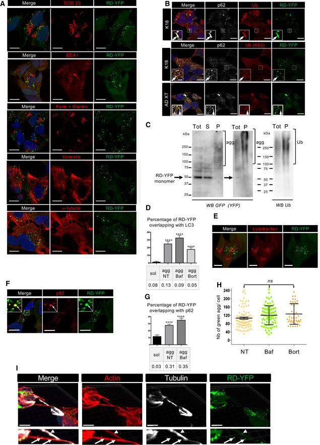
RD‐YFP SH cells were challenged with non‐labeled K18 fibrils for 2 days before fixation, saponin permeabilization, and staining with antibodies recognizing, respectively, TOM 20, EEA1, Furin + Giantin, vimentin, alpha‐tubulin, or WGA. Representative deconvoluted confocal images are presented, and blue staining is DAPI in the merged pictures; and scale bars are 10 μm.
Representative confocal images (of three independent experiments) of RD‐YFP aggregates overlapping with p62 and ubiquitin, induced either by synthetic K18 fibrils or by AD‐derived extracts as indicated on the left. RD‐YFP SH cells were challenged with non‐labeled K18 fibrils for 2 days or AD XT for 4 days before fixation, saponin permeabilization, and staining with antibodies recognizing all types of ubiquitin chains (Ub) or K63‐linked ubiquitin chains (Ub [K63]) and p62 (white). Insets are threefold enlargements of the boxed regions, showing colocalizations of Ub, p62, and RD‐YFP; scale bars are 10, 2 μm in insets.
Ubiquitination of RD‐YFP aggregates. Frozen cell pellets of RD‐YFP SH cells treated with K18 fibrils and grown for 4 days were thawed on ice and cells were lysed in PBS‐Triton X‐100 0.05%, and next total extracts (tot) were ultracentrifugated at 100,000 g to separate soluble material (S) from pellets (P) corresponding to insoluble material, including aggregates, shown by brackets in the WB of the left panel (4–12% gel in MES buffer, denaturation in 1% Laemmli without reducing agent). Tot and P fractions were loaded again, and the same membrane was blotted consecutively with antibodies against ubiquitin (right panel) and RD‐YFP (GFP). Ubiquitinated material and aggregates are shown with brackets, and the arrow points to monomeric RD‐YFP. MW (kDa) is indicated for each gel.
Quantification of the colocalization between RD‐YFP and LC3 in various conditions. Cells were treated as in Fig 3A, except that antibody recognizing LC3 was used, and quantifications were performed as in 3B. The graph represents the mean percentage (+ SEM) of green material overlapping with LC3, and the number of cells analyzed was 14, 18, 14, and 24, respectively, for each condition over two experiments. PCC is indicated below the graph. Statistically significant differences were compared to the soluble conditions (one‐way ANOVA and Tukey's post hoc test, [****P = 1.34E−07, 5.79E−10, 8.17E−07]).
Representative confocal images of RD‐YFP SH cells, challenged with non‐labeled K18 fibrils for 2 days. LysoTracker (red) was added to the culture 30 min before fixation, and scale bars are 10 μm.
Representative picture of RD‐YDP SH cells, 14 days after challenging with non‐labeled fibrils and processed for immunofluorescence as in Fig 3A. Insets are threefold enlargements of the boxed region; white arrows point to colabelings; scale bars are 10 μm.
Quantification of colocalization of RD‐YFP material with p62‐positive structures after 7 or 14 days of culture. Confocal pictures were analyzed in 3D with Imaris software, as in Fig 4B. Below the graph (mean percentage with SEM) is indicated the corresponding Pearson's correlation coefficient (PCC). The number of cells analyzed in each condition over three independent experiments was 39, 81, and 65, respectively. Statistically significant differences are compared to the soluble conditions (one‐way ANOVA and Tukey's post hoc test [****P = 6.13E−07 and 7.85E−08 for NT and Baf, respectively]). Note that the differences between agg NT and BafA1 are not significant, for percentage of overlapping and for PCC.
Analysis of the number of green dots per cell among the population of cells containing RD‐YFP aggregates after treatment with bafilomycin A1 or bortezomide. Cells were treated and imaged as described in Fig 3A, and analysis of 63× images was performed using spot detector wizard (scale 3, threshold 80) under Icy software, with a total number of analyzed cells over three independent experiments of 95, 87, and 39 for each condition, respectively. Each analyzed cell is represented on the dot plot, and the bars indicate the means ± SEM (respectively, 106, 120, and 126). Statistical analysis was performed by one‐way ANOVA and Tukey's post hoc test, and all the pairwise comparisons were not significant (ns). Note that the difference in mean aggregate number compared to Fig 4 is because of the different acquisition conditions (63× instead of 40×).
RD‐YFP aggregates inside a TNT positive for actin (phalloidin labeled, red) and negative for tubulin (white). After treatment with unlabeled K18 fibrils, RD‐YFP was plated on coverslips for 24 h and treated with trypsin for 1 min before fixation and immunofluorescence. The 3D view shows eight slices covering 2.45 μm. Below each panel is a twofold magnification of the TNT area. Arrows show aggregates inside actin‐only‐positive TNTs, and arrowhead shows an aggregate inside an actin and tubulin‐positive connection. Scale bars are 10 μm. The average diameter of tubulin and actin‐containing connections (as measured based on phalloidin labeling at the level of the aggregate) was 0.6 μm (SD 0.11, n = 8), whereas the actin‐only‐containing connections were thinner (0.40 μm, SD: 0.05, n = 4).
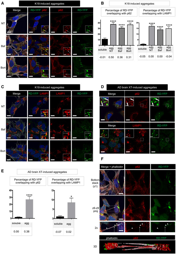
RD‐YFP SH cells were challenged with non‐labeled K18 fibrils, incubated 2 days later with bafilomycin A1 (second line of panels), bortezomide (bottom panels), or left non‐treated (NT, upper panels) for 4 h before fixation, saponin permeabilization, and staining with antibody recognizing p62 (red) and WGA (white in left panels). Images are confocal pictures after deconvolution (63×, zoom 1.8, px size = 60 nm, slice of 0.43 μm) representative of three independent experiments. Insets are threefold enlargements of the boxed regions of second column; white arrows point to colabeling; scale bars are 10, 2 μm in insets.
Quantification of colocalization of RD‐YFP material with p62‐positive structures (left graph) or LAMP1‐positive vesicles (right) upon K18 fibril‐induced aggregation. Confocal pictures were analyzed in 3D with Imaris software from pictures obtained as in (A), and the graphs represent the mean percentage (+ SEM) of green material overlapping with p62 or LAMP1: aggregates if cells have been converted (agg) or soluble material otherwise. Below each graph, the corresponding Pearson's correlation coefficient (PCC) is indicated. The number of cells analyzed over two independent experiments is 40, 51, 63, and 34 for each respective condition for p62, 36, 59, 44, and 27 for LAMP1. Statistically significant differences were then compared to the soluble conditions (one‐way ANOVA and Tukey post hoc test [****P = 1.33E‐17, 2.57E‐18, and 2.05E‐20, respectively, for p62, 3.44E‐16, 1.21E‐13, and 1.24E‐13 for LAMP1]). Note that the differences between agg NT, BafA1, and Bort were not significant neither for percentage of overlapping nor for PCC, with both p62 and LAMP1.
As in (A), except that anti‐LAMP1 antibody was used; scale bars are 10, 2 μm in the insets.
RD‐YFP SH cells were challenged with AD‐derived brain extracts, trypsinized, and replated 3 days later for an additional 24h before fixation, saponin permeabilization, and staining with antibody recognizing p62 or LAMP1 (in red). Images are confocal pictures (63×, zoom 1.6, px size = 60 nm, slice of 0.43 μm) representative of two independent experiments. Insets are threefold enlargements of the boxed regions; white arrows point to colabeling; scale bars are 10, 2 μm in the insets.
Quantification of colocalization of RD‐YFP material with p62‐positive structures (left graph) or LAMP1‐positive vesicles (right) upon AD extract‐induced aggregation. Confocal pictures were analyzed in 3D with Imaris software from pictures obtained as in (D), and the graphs represent the mean percentage (+ SEM) of green material overlapping with p62 or LAMP1: aggregates if cells have been converted (agg) or soluble material otherwise. Below each graph, the corresponding Pearson's correlation coefficient (PCC) is indicated. The number of cells analyzed over two independent experiments is 21 (sol) and 27 (agg) for p62, and 12 (sol) and 17 (agg) for LAMP1. Statistically significant differences were then compared to the soluble conditions (two‐tailed t‐test, ****P = 5.62E‐06, *P = 0.013).
Confocal pictures of RD‐YFP cells, treated with bortezomide and labeled as in (A), except that phalloidin‐Texas Red was incubated together with the secondary Alexa 647 antibody. Upper panels are the bottom slice corresponding to the substrate‐attached surface of cells (z1), and below are projections of slices 6–9 of the same pictures (z6–z9, not attached to the substrate). Below is a twofold magnification of the area framed in the merged projection, showing a TNT. White arrows point to overlapping between RD‐YFP aggregates and p62, and arrowheads to aggregates not colocalizing with p62 inside the TNT; scale bars are 10, 5 μm in the insets. Bottom is a 3D reconstruction (using Imaris software) of the same region.
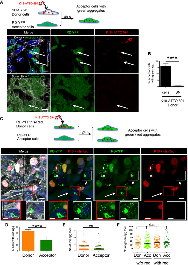
Below the schematic representation of the experiment are representative confocal images of 2‐day cocultures of RD‐YFP SH cells (acceptor cells) with K18‐ATTO 594 fibril‐treated SH‐SY5Y cells (donor cells, upper panel). Bottom panels are acceptor cells cultured with the supernatant of K18‐ATTO 594 fibril‐treated SH‐SY5Y cells (donor SN). WGA (white) labels cell membrane and DAPI the nuclei in the merge panels. Arrows point to cells with green and red aggregates; scale bars are 20 μm.
Quantification of seeding after transfer in RD‐YFP SH cells in the experiments described in (A), depending on the condition (donor cells or donor SN). Analysis was performed using ICY software, and data represent the number of aggregate‐containing cells over the total number of green cells ± SD (the total number of RD‐YFP cells analyzed over three independent experiments was 1,011 for coculture and 1,265 for SN) with statistical analysis by two‐tailed unpaired t‐test (****P = 4.18E‐07).
Below the schematic representation of the experiment are representative confocal images showing maximal intensity projections of six z‐slices (covering 2 μm of thickness) of 24‐h coculture of RD‐YFP SH cells (acceptor cells) with RD‐YFP SH cells expressing nls‐Red and challenged with K18‐ATTO 594 fibrils (donor cells). WGA (white) labels cell membrane and DAPI the nuclei in the merge panel. Stars label donor cells containing green and red aggregates, arrows indicate an acceptor cell with green and red aggregates, and the arrowheads show an acceptor cell with green aggregates but devoid of red fibrils. Below are twofold enlargement of the respective framed cells. The apparent discontinuity in the picture corresponds to the boundary between two adjacent tiles. Scale bars are 10 and 5 μm in the enlargements.
Analysis using ICY software of the percentage of cells containing red fibrils among the population of cells containing green aggregates. The graph shows the mean percentages with SEM (respectively, 66.3 and 36.9% for donor and acceptor cells), and statistical analysis was performed by two‐tailed unpaired t‐test (****P = 3.65E−05).
Dot plot showing the number of red fibrils per cell with SEM among the population of cells containing green and red aggregates. Each analyzed cell is represented (note that because of the chosen scale, 6 data points are outside the axis limits), the bars indicate the means ± SEM (respectively, 3.9 and 1.9 for donor and acceptor cells), and statistical analysis was performed by two‐tailed unpaired t‐test (**P = 0.0015).
Analysis of the number of green dots per cell among the population of cells containing green aggregates. Each analyzed cell is represented on the dot plot, and the bars indicate the means ± SEM (respectively, 30.2, 26.1, 32.0, and 32.2). Statistical analysis was performed by one‐way ANOVA, and Tukey post hoc test and all the pairwise comparisons were not significant (n.s.).
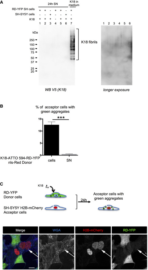
Conditioned medium of cells treated with K18 fibrils is devoid of K18 fibrils. Twenty‐four‐hour conditioned media (1 ml) of cells (SH‐SY5Y or RD‐YFP SH) treated or not with K18 as indicated, providing from independent experiments, were ultracentrifuged at 100,000 g for 1 h at 4°C. Pellets containing insoluble material were solubilized in 1% SDS‐containing Laemmli without reducing agent and analyzed by WB for the presence of K18 (detected with anti‐V5 antibody). As positive control, the same volume of fibril‐containing medium, collected at the end of the 6‐h incubation on cells (i.e., containing fibrils that were not uptaken by cells), was processed the same way (lane 7). The K18 ladder corresponding to the fibrils is indicated by brackets. Right is overexposure of the lanes 1–6 of the membrane.
Quantification of the percentage of RD‐YFP SH acceptor cells with insoluble RD‐YFP, depending on the condition (12.5% for donor cells and 0.37% for donor SN) in the experiment described in Fig 4C. Analysis was performed using ICY software, and data represent the number of aggregate‐containing cells over the total number of green cells without red nuclei + SEM (the total number of acceptor cells analyzed over two independent experiments was 1,788 for coculture and 1,028 for SN) with statistical analysis by two‐tailed unpaired t‐test (***P = 0.0006).
Visualization of the direct transfer of endogenously formed RD‐YFP aggregates to SH‐SY5Y cells. Above the pictures is a schematic representation of the experiment. Donor RD‐YFP SH cells expressing aggregates obtained 2 days after treatment with non‐labeled K18 fibrils were cocultured for 24 h with SH‐SY5Y cells first transfected with H2B‐mCherry expression vector. The images are Z‐stack projections covering nine slices (each 0.43 μm), and similar experiments were performed three times. Transferred RD‐YFP aggregate is indicated by the white arrow, and single‐channel pictures are grayscale images; and scale bar is 10 μm.
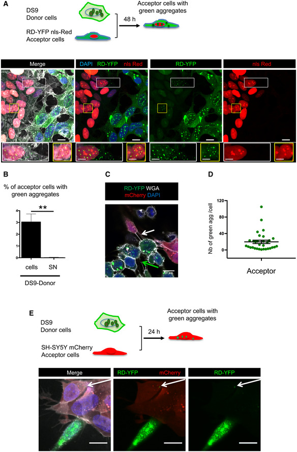
Two‐day coculture of SH‐SY5Y cells expressing RD‐YFP and nls‐Red (acceptor cells) with DS9 cells (donor cells). Below the schematic representation of the experiment are representative confocal images showing maximum intensity projections of six z‐slices (covering 2 μm of thickness). In the merged images, white is WGA labeling, green is RD‐YFP, red is nls‐Red nuclei, and nuclei are stained in blue with DAPI; scale bars are 10, 5 μm in the enlarged boxes. Below each image are twofold enlargements of the corresponding boxed areas.
Quantification of experiment described in (A), giving the percentage of converted nls‐Red‐expressing RD‐YFP SH cells after coculture with DS9 cells or SN (donor cells or donor SN). Analysis was performed using ICY software, data represent the number of converted acceptor cells over the total number of nls‐Red‐expressing RD‐YFP SH cells + SEM, and means are 3.04 (donor cells) and 0.03 (donor SN). The total number of RD‐YFP SH cells analyzed over three independent experiments was 1,923 for coculture and 1,654 for SN, statistical analysis by two‐tailed unpaired t‐test (**P = 0.0075).
Representative confocal image showing a TNT connecting two DS9 cells (green arrow) or connecting one RD‐YFP nls‐Red SH cell and one DS9 cell (white arrow). To improve visualization of the TNTs, cells were incubated for 1 min with trypsin just before PFA fixation.
Mean number of green dots per cell ± SEM among the population of cells containing green aggregates in the experiments described in A. Cell counts were performed over three independent experiments using spot detector wizard under Icy software (scale 1), with a total number 30 acceptor cells analyzed. The scatter dot plot shows each cell as a circle, and the mean (19.7) ± SEM to compare to Fig 4F.
Visualization of the direct transfer of native RD‐YFP aggregates from DS9 to SH‐SY5Y cells. Above the pictures is a schematic representation of the experiment. Donor DS9 cells were cocultured for 24 h with SH‐SY5Y cells first transfected with mCherry expression vector. Transferred RD‐YFP aggregate is indicated by the white arrow, and white is WGA in merge; scale bars are 10 μm.
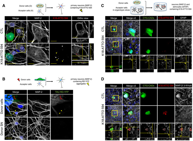
Below the schematics of the experiment are representative confocal images of donor neuron‐like cells (CAD cells labeled with Cell Tracker Green [CTG]) and acceptor primary neurons after 24 h in coculture. The upper panels show control conditions (non‐challenged CAD cells, CTL), and the bottom panels show donor CTG‐CADs that were loaded with K18‐ATTO 594 fibrils prior to coculture with primary cortical neurons. The images are representative Z‐stack projections covering the whole cell body of donor and acceptor cells. In the merged images, white show neurons labeled with MAP‐2, green are CTG‐labeled donor CAD cells, red corresponds to K18‐ATTO 594 puncta, and nuclei are stained in blue. The single‐channel pictures are grayscale images. Yellow arrowheads point to K18 puncta inside acceptor cells. MAP‐2 and K18‐ATTO 594 panels are threefold enlargements of the boxed regions in the merged pictures. On the right are the orthogonal views of the same regions covering 14 slices. Scale bars are 20 μm in the merge panels, and 5 μm in the insets and orthogonal views. See also Fig EV6.
Below the schematics of the experiment are representative confocal images of acceptor primary neurons (labeled by MAP‐2) cultured with donor cells, consisting of RD‐YFP SH cells, first K18‐challenged for 2 days, therefore expressing RD‐YFP aggregates (upper panels) or with supernatant (SN) of donor cells (lower panels) after 24 h. The single‐channel pictures are grayscale images. Yellow arrowheads point to Tau RD‐YFP puncta inside acceptor cells, and red arrowheads point to aggregates inside donor cells. Scale bars are 20 μm.
Below the schematics of the coculture experiment are representative confocal images of neuron‐like cells (CTG‐CADs as in A) growing on top of organotypic slices (n = 6), in which the astrocytes were labeled with GFAP. The upper panels show control CTG‐CADs and the middle panels show donor CTG‐CADs loaded with K18‐ATTO 594 fibrils, cocultured with an acceptor hippocampal slice. The images are representative Z‐stack projections covering the whole cell body of donor cells. In the merged images, white are acceptor astrocytes (GFAP‐positive), green are donor CTG‐CADs, red are K18‐ATTO 594 puncta, and nuclei are stained in blue. Insets are threefold enlargements of the boxed region in the merged picture. The orthogonal views of the bottom panels show 25 slices of K18‐ATTO 594 fibrils in donor cells (1), or transfer of K18‐ATTO 594 fibrils from donor CTG‐CADs to hippocampal astrocytes of the organotypic slice (2–5). Yellow arrowheads point to Tau puncta inside acceptor astrocytes. Orthogonal views show each of the five K18‐ATTO 594‐positive puncta contained inside acceptor cells as indicated in the inset of the middle panel. Scale bars are 100 μm in the merged panel and 10 μm in the insets.
Same as in C, but in this case the neurons in the slices were labeled with the dendrite marker MAP‐2 and the axonal marker β‐III‐tubulin (white), and the orthogonal views show 26 slices. Scale bars are 100 μm in the merged panel and 10 μm in the insets.
References
-
- Abounit S, Zurzolo C (2012) Wiring through tunneling nanotubes–from electrical signals to organelle transfer. J Cell Sci 125: 1089–1098 - PubMed
-
- Abounit S, Delage E, Zurzolo C (2015) Identification and characterization of tunneling nanotubes for intercellular trafficking. Curr Protoc Cell Biol 67: 12.10.1–12.10.21 - PubMed
Publication types
MeSH terms
Substances
Grants and funding
LinkOut - more resources
Full Text Sources