Review
. 2021 Jan;298(1):3-17.
doi: 10.1148/radiol.2020192791. Epub 2020 Nov 17.

Next-Generation Hardware Advances in CT: Cardiac Applications

Affiliations
Review

Next-Generation Hardware Advances in CT: Cardiac Applications

Alan C Kwan et al. Radiology. 2021 Jan.

Abstract

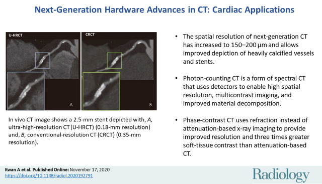
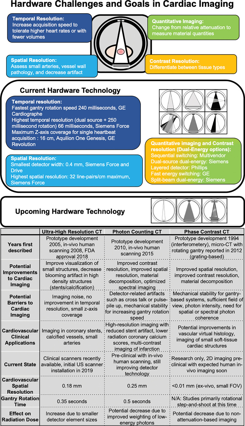
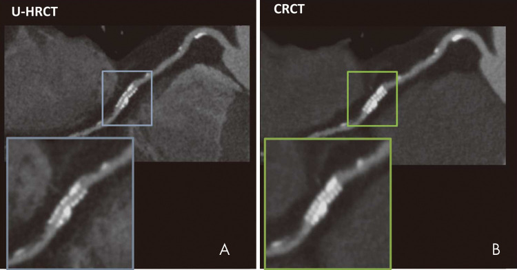
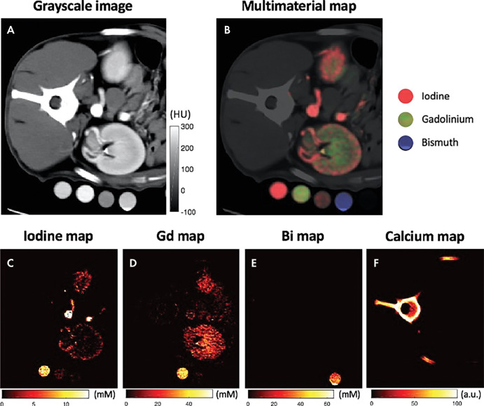
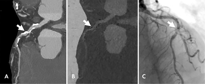
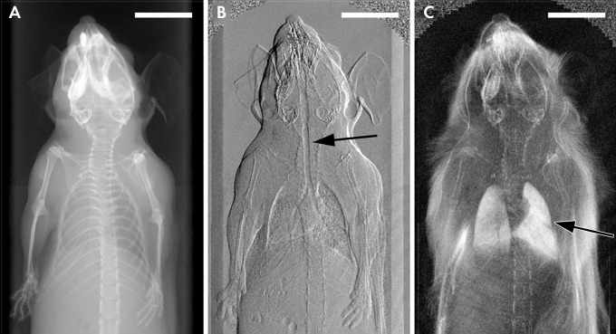
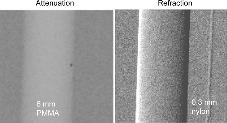
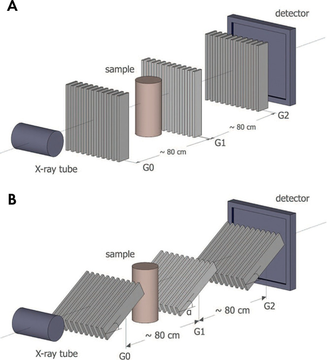
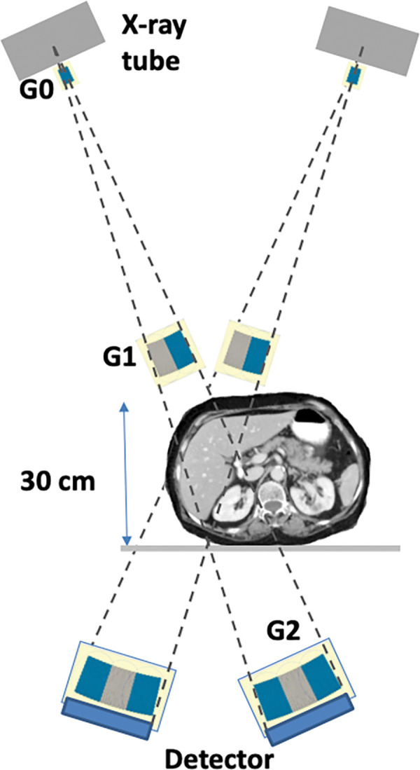
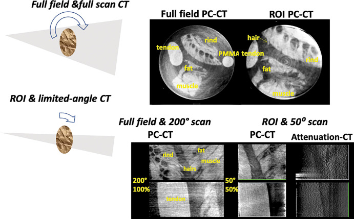
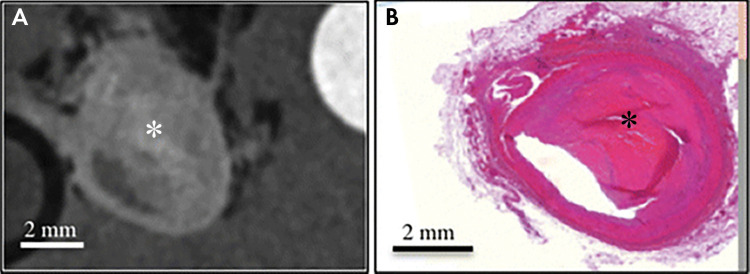
Impending major hardware advances in cardiac CT include three areas: ultra-high-resolution (UHR) CT, photon-counting CT, and phase-contrast CT. Cardiac CT is a particularly demanding CT application that requires a high degree of temporal resolution, spatial resolution, and soft-tissue contrast in a moving structure. In this review, cardiac CT is used to highlight the strengths of these technical advances. UHR CT improves visualization of calcified and stented vessels but may result in increased noise and radiation exposure. Photon-counting CT uses multiple photon energies to reduce artifacts, improve contrast resolution, and perform material decomposition. Finally, phase-contrast CT uses x-ray refraction properties to improve spatial and soft-tissue contrast. This review describes these hardware advances in CT and their relevance to cardiovascular imaging.


Figures

None
Graphical abstract
Clinical challenges to cardiac CT, including temporal, spatial, and contrast resolution, and quantitative imaging. Current technologic approaches and upcoming approaches with ultra-high-resolution CT, photon-counting CT, and phase-contrast CT with potential clinical cardiac applications. FDA = Food and Drug Administration, FOV = field of view, N/A = not applicable.
Figure 1:
Clinical challenges to cardiac CT, including temporal, spatial, and contrast resolution, and quantitative imaging. Current technologic approaches and upcoming approaches with ultra-high-resolution CT, photon-counting CT, and phase-contrast CT with potential clinical cardiac applications. FDA = Food and Drug Administration, FOV = field of view, N/A = not applicable.
In vivo CT image shows a 2.5-mm stent depicted with, A, ultra-high-resolution CT (U-HRCT) (0.18-mm resolution) and, B, conventional-resolution CT (CRCT) (0.35-mm resolution). (Reprinted, with permission, from reference 30.)
Figure 2:
In vivo CT image shows a 2.5-mm stent depicted with, A, ultra-high-resolution CT (U-HRCT) (0.18-mm resolution) and, B, conventional-resolution CT (CRCT) (0.35-mm resolution). (Reprinted, with permission, from reference .)
Multicontrast photon-counting CT images in a canine abdomen. A, Gray-scale CT image obtained using photons with single-energy bin. B, Multimaterial map obtained using multienergy reconstruction, labeling iodine, gadolinium, and bismuth with different colors, resulting in different distributions. C, Iodine map alone. D, Gadolinium (Gd)-enhanced map alone. E, Bismuth (Bi) map alone. F, Calcium map alone. (Reprinted, with permission, from reference 55.)
Figure 3:
Multicontrast photon-counting CT images in a canine abdomen. A, Gray-scale CT image obtained using photons with single-energy bin. B, Multimaterial map obtained using multienergy reconstruction, labeling iodine, gadolinium, and bismuth with different colors, resulting in different distributions. C, Iodine map alone. D, Gadolinium (Gd)-enhanced map alone. E, Bismuth (Bi) map alone. F, Calcium map alone. (Reprinted, with permission, from reference .)
Images in a 92-year-old woman with chest pain. A, Dual-energy coronary CT angiogram. B, Material decomposition–based calcium suppression and, C, corresponding invasive coronary angiogram show a patent lumen visualized with calcium suppression imaging. Arrow indicates the same middle left anterior descending coronary lesion. (Reprinted, with permission, from reference 63.)
Figure 4:
Images in a 92-year-old woman with chest pain. A, Dual-energy coronary CT angiogram. B, Material decomposition–based calcium suppression and, C, corresponding invasive coronary angiogram show a patent lumen visualized with calcium suppression imaging. Arrow indicates the same middle left anterior descending coronary lesion. (Reprinted, with permission, from reference .)
X-ray images in a mouse obtained with, A, standard attenuation-based imaging, B, phase-contrast imaging, and, C, dark-field imaging. Arrow indicates regions of enhanced contrast in the trachea (B) and lungs (C). (Reprinted, with permission, from reference 69.)
Figure 5:
X-ray images in a mouse obtained with, A, standard attenuation-based imaging, B, phase-contrast imaging, and, C, dark-field imaging. Arrow indicates regions of enhanced contrast in the trachea (B) and lungs (C). (Reprinted, with permission, from reference .)
Attenuation-based radiograph and phase-contrast refraction radiograph of a poly(methyl methacrylate) (PMMA) rod and a 0.3-mm nylon filament immersed in a 5-cm-thick water bath. The images were obtained at 60 kVp with a glancing angle interferometer. The computed radiation dose is 2 mGy absorbed dose. The thin filament is invisible on the conventional image (left) but has good contrast with refraction (right).
Figure 6:
Attenuation-based radiograph and phase-contrast refraction radiograph of a poly(methyl methacrylate) (PMMA) rod and a 0.3-mm nylon filament immersed in a 5-cm-thick water bath. The images were obtained at 60 kVp with a glancing angle interferometer. The computed radiation dose is 2 mGy absorbed dose. The thin filament is invisible on the conventional image (left) but has good contrast with refraction (right).
A, Talbot-Lau interferometer set-up with, B, glancing angle grids. G = grating. (Reprinted, with permission, from reference 75.)
Figure 7:
A, Talbot-Lau interferometer set-up with, B, glancing angle grids. G = grating. (Reprinted, with permission, from reference .)
High-energy region-of-interest phase-contrast tomosynthesis system for the internal organs based on the glancing angle interferometer design. G = grating.
Figure 8:
High-energy region-of-interest phase-contrast tomosynthesis system for the internal organs based on the glancing angle interferometer design. G = grating.
Top: Full-field and region of interest (ROI) phase-contrast CT (PC-CT) scans of fresh pig soft tissues in water at diagnostic energy. The imaged section is 25 mm in diameter. Bottom: Full-field and full-scan phase-contrast CT images and simultaneous region-of-interest and limited-angle phase-contrast tomosynthesis of soft tissues in water. Also shown is the conventional attenuation–based tomosynthesis image, indicating much less soft-tissue contrast than in the phase-contrast image. PMMA = poly(methyl methacrylate).
Figure 9:
Top: Full-field and region of interest (ROI) phase-contrast CT (PC-CT) scans of fresh pig soft tissues in water at diagnostic energy. The imaged section is 25 mm in diameter. Bottom: Full-field and full-scan phase-contrast CT images and simultaneous region-of-interest and limited-angle phase-contrast tomosynthesis of soft tissues in water. Also shown is the conventional attenuation–based tomosynthesis image, indicating much less soft-tissue contrast than in the phase-contrast image. PMMA = poly(methyl methacrylate).
Ex vivo images of complex fibrous material (*) within plaque in the right coronary artery obtained, A, with phase-contrast CT and, B, at histology. (Reprinted, with permission, from reference 95.)
Figure 10:
Ex vivo images of complex fibrous material (*) within plaque in the right coronary artery obtained, A, with phase-contrast CT and, B, at histology. (Reprinted, with permission, from reference .)

References

    1. Schmidt B, Grant K, Flohr TG, Allmendinger T. Cardiac CT Platforms: State of the Art. In: Schoepf UJ, ed. CT of the Heart. 2nd ed. New York, NY: Humana/Springer, 2019; 51–67.
    1. Flohr TG, Allmendinger T, Bruder H, Schwemmer C, Kappler S, Schmidt B. Future Technological Advances in Cardiac CT. In: Schoepf UJ, ed. CT of the Heart. 2nd ed. New York, NY: Humana/Springer, 2019; 873–892.
    1. Schoepf UJ, ed. CT of the Heart. 2nd ed. New York, NY: Humana/Springer, 2019.
    1. Dodge JT, Jr, Brown BG, Bolson EL, Dodge HT. Lumen diameter of normal human coronary arteries. Influence of age, sex, anatomic variation, and left ventricular hypertrophy or dilation. Circulation 1992;86(1):232–246. - PubMed
    1. Ahmadi A, Argulian E, Leipsic J, Newby DE, Narula J. From Subclinical Atherosclerosis to Plaque Progression and Acute Coronary Events: JACC State-of-the-Art Review. J Am Coll Cardiol 2019;74(12):1608–1617. - PubMed

Publication types

MeSH terms