

doi: 10.1055/s-0040-1713941.
Epub 2020 Sep 9.
Surgical Approaches to the Orbit: A Neurosurgical Perspective
Affiliations
- PMID: 33209566
- PMCID: PMC7661317
- DOI: 10.1055/s-0040-1713941
Item in Clipboard
Surgical Approaches to the Orbit: A Neurosurgical Perspective
J Neurol Surg B Skull Base.
2020 Aug.
Abstract
Orbital pathologies can be complex to manage surgically. In this article, we describe some of the most common and relevant approaches to orbital tumours. For each approach we describe the appropriate indications, surgical technique, potential complications, and illustrate a case example.
Keywords: EEA; Orbitotomy; TONES; endoscopy; orbit; skull base.
Thieme. All rights reserved.
Conflict of interest statement
Conflict of Interest None declared.
Figures
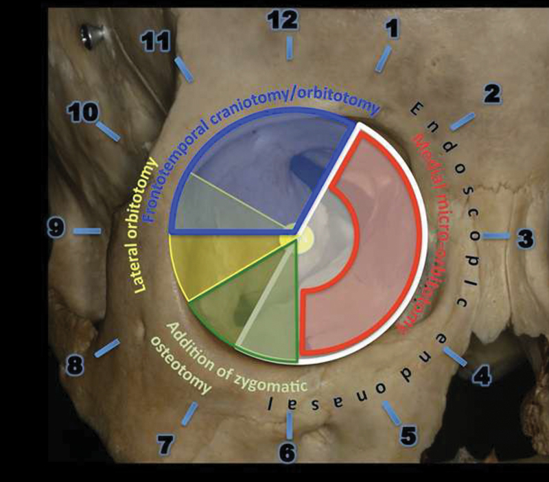
Drawing shows the algorithm developed and published in 2015. The right orbit is used for demonstration of the clock model. A medial transconjunctival approach gives access to the anterior orbit from 1 to 6 o'clock. An endoscopic endonasal approach enables access to the apical compartments, middle and posterior aspects of the orbit between 1 and 7 o'clock. Lateral microorbitotomy enables access to the orbit from 8 to 10 o'clock. A frontotemporal craniotomy with orbital osteotomy gives orbital access from 9 to 1 o'clock and a zygomatic osteotomy extends this access from 6 to 8 o'clock. (Reprinted with permission from Paluzzi A, Koutourousiou M, Tormenti M, et al. “Round-the-Clock” Surgical Access to the Orbit. Journal of Neurological Surgery Part B: Skull Base. 2014;73(S 02):12–24. doi:10.1055/s-0032-1314033)

An illustration of surgical entry sites into the orbit.

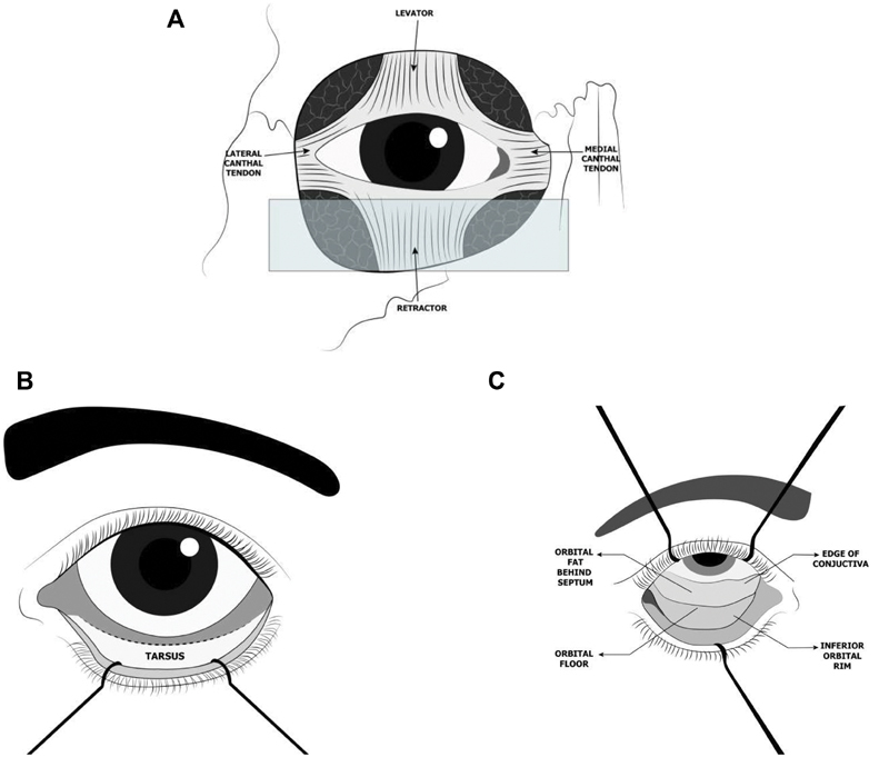
Images demonstrating a medial microorbitotomy. (
A
) This approach gives access to lesions located anterior and medial in the orbit. (
B
) An eyelid retractor is placed, and local anesthetic injected where the peritomy will be performed. (
C
) After the conjunctiva is incised around the cornea and relaxing conjunctival incisions are made, the medial rectus muscle is detached and (
D
) retracted medially with a suture. (
E
) The globe is retracted laterally and the intraconal fat exposed. (
F
) After the lesion has been excised, the medial rectus muscle is reattached at its insertion site on the globe with a 6–0 absorbable suture, and the conjunctiva is closed with interrupted sutures. (Reprinted with permission from Paluzzi A, Koutourousiou M, Tormenti M, et al. “Round-the-Clock” Surgical Access to the Orbit. Journal of Neurological Surgery Part B: Skull Base. 2014;73(S 02):12–24. doi:10.1055/s-0032-1314033)

(
A
) Transconjunctival incision - horizontal incision at 3– to 4 mm inferior to lower eyelid margin, approximately 2.5 cm. (
B
) Demonstration of some of Horner's muscle.

Schematic representation of approaching the medial orbit through a transcaruncular approach. (
A
) Dissection begins between the caruncle (globular nodule in the medial canthus of the eye) and plica semilunaris (fold in the bulbar conjunctiva of the medial cantus of the eye). (
B
) Dissection extends into the subperiosteal space. (Adapted from Graham et al.)

The illustration demonstrates the close proximity of the central retinal artery to the optic nerve and the globe. The ophthalmic artery forms the first branch of the internal carotid artery (ICA). The ophthalmic artery splits into the posterior ciliary and central retinal arteries that supply the eye.

A coronal computed tomography (CT) image demonstrates the position of a foreign body located between the 2 and 3 o'clock positions in the anterior orbit.

The figure demonstrates the safe zone for lateral orbital incision described by Schmidt et al.
This can be defined by using the predicted paths of the zygomatic and temporal branch of facial. The temporal nerve in their study had a mean distance of 2.8 cm superior to the lateral canthus and the zygomatic nerve had a mean distance 1.7 cm inferior to the temporal nerve at the point of insertion into orbicularis oculi muscle. (Adapted from Schmidt et al.
15
)

Endoscopic endonasal approach. (
A
) Skull showing the clock model showing the extent of the orbit that can be exposed through this approach. (
B
) The insertions of the rectus muscles to the globe are identified and controlled with vessel loops. (
C
) Endoscopic view of the medial aspect of the orbital apex after a portion of the periorbita has been excised. The internal carotid artery (ICA) is visible medially. The window between medial and inferior rectus muscles is “closed.” (
D
) After external retraction on the medial and inferior rectus muscles by pulling the respective vessel loops, the surgical window in now “open” and the tumor is identified and (
E
) excised. (
F
) The periorbital defect is covered with a free mucosal graft harvested from the removed ipsilateral middle turbinate. (Reprinted with permission from Paluzzi A, Koutourousiou M, Tormenti M, et al. “Round-the-Clock” Surgical Access to the Orbit. Journal of Neurological Surgery Part B: Skull Base. 2014;73(S 02):12–24. doi:10.1055/s-0032-1314033)

(
A
) Coronal computed tomography images (bone window) demonstrating a medial orbital osteoma that was completely excised. (
B
) Coronal magnetic resonance imaging illustrating an orbital apex angioleiomyoma. (Reprinted with permission from Paluzzi A, Koutourousiou M, Tormenti M, et al. “Round-the-Clock” Surgical Access to the Orbit. Journal of Neurological Surgery Part B: Skull Base. 2014;73(S 02):12–24. doi:10.1055/s-0032-1314033)

Lateral orbitotomy. (
A
) The approach is ideal for lesions located in the 8 to 10 o'clock position lateral to the optic nerve. (
B
) Small cantholysis incision is made with Steven's scissors along the skin crease. (
C
) Temporalis muscle is detached and retracted laterally; the lateral wall of the orbit can be appropriately exposed if adequate retraction is present. Reciprocating saw is used to perform the osteotomies. (
D
) The orbitotomy has been completed and a monopolar was used to cut the last fibers of the temporalis muscle. (
E
) Periorbita is opened and the tumor is resected. (
F
) Penrose drain secured in place. (Reprinted with permission from Paluzzi A, Koutourousiou M, Tormenti M, et al. “Round-the-Clock” Surgical Access to the Orbit. Journal of Neurological Surgery Part B: Skull Base. 2014;73(S 02):12–24. doi:10.1055/s-0032-1314033)

Coronal computed tomography image demonstrating an extraconal pleomorphic adenoma of the lacrimal gland in the 8 to 10 o'clock position amenable to a lateral orbitotomy. (Reprinted with permission from Paluzzi A, Koutourousiou M, Tormenti M, et al. “Round-the-Clock” Surgical Access to the Orbit. Journal of Neurological Surgery Part B: Skull Base. 2014;73(S 02):12–24. doi:10.1055/s-0032-1314033)

Frontotemporal craniotomy with orbitozygomatic osteotomy. (
A
) Clock model showing the extent of the orbit that can be exposed through this approach. (
B
) The frontotemporal craniotomy (first piece) has been cut, the temporalis muscle dissected off its anterior attachment and retracted posteriorly, and a malleable retractor inserted between the orbital roof and the periorbita. (
C
) While protecting the orbit content on one side of the orbital roof and the frontal lobe on the other side with malleable retractors, the final cut over the orbital roof is made with a high-speed drill going laterally toward the inferior orbital fissure. (
D
) The “second piece” of the orbitozygomatic craniotomy is removed exposing (
E
) periorbita and periorbital fat. (
F
) After retraction of muscles and periorbital fat with cotton-tipped applicators, the tumor comes into view (photo taken with operative microscope). (Reprinted with permission from Paluzzi A, Koutourousiou M, Tormenti M, et al. “Round-the-Clock” Surgical Access to the Orbit. Journal of Neurological Surgery Part B: Skull Base. 2014;73(S 02):12–24. doi:10.1055/s-0032-1314033)

(
A
) Incision for supraorbital craniotomy marked on the right eyebrow. (
B
) Supraorbital craniotomy has been performed preserving the orbital rim and, medially, the supraorbital nerve (arrow). (
C
) Gentle retraction is applied to the frontal lobe after removal of cerebrospinal fluid from the opticocarotid recess. (
D
) View after fenestration of a suprasellar arachnoid cyst. (
E
) Closure with 5.0 ethylon.

(
A
) Preoperative coronal, postcontrast T1 magnetic resonance imaging (MRI) scan demonstrating a suprasellar arachnoid cyst (arrow) compressing and displacing the optic chiasm. (
B
) Postoperative MRI scan 2 years after fenestration of the arachnoid cyst via a supraorbital eyebrow craniotomy

Coronal T2 magnetic resonance imaging demonstrating an intraconal cavernous hemangioma located in the 12 to 1 o'clock position resected through a frontotemporal craniotomy and orbitotomy. (Reprinted with permission from Paluzzi A, Koutourousiou M, Tormenti M, et al. “Round-the-Clock” Surgical Access to the Orbit. Journal of Neurological Surgery Part B: Skull Base. 2014;73(S 02):12–24. doi:10.1055/s-0032-1314033)

Cavernous angioma located in the 6 to 8 o'clock position managed initially with endoscopic orbital decompression followed by a frontotemporal craniotomy with orbitozygomatic osteotomy. (Reprinted with permission from Paluzzi A, Koutourousiou M, Tormenti M, et al. “Round-the-Clock” Surgical Access to the Orbit. Journal of Neurological Surgery Part B: Skull Base. 2014;73(S 02):12–24. doi:10.1055/s-0032-1314033)

The diagram illustrates the four access quadrants of the orbit. (
A
) Superior eyelid crease (SLC), (
B
) precaruncular (PC), (
C
) preseptal lower eye lid (PS), (
D
) lateral retrocanthal (LRC) approaches. (Adapted from Ramakrishna et al.
36
)

The images demonstrate the superior eyelid crease (SLC) approach. (
A
) The shaded area shows the area of the orbit targeted in the SLC approach. (
B
) Exposure of the orbital rim followed by incision of the periosteum at the inferior aspect of the rim. Between the periosteum and orbital roof, a cotton-tipped applicator can be used to aid with retraction. An endoscope is used to proceed with dissection. (Adapted from Moe et al.
34
)

Precaruncular (PC) approach is demonstrated. (
A
) Targeted area is demonstrated. (
B
) Demonstrates a conjunctival incision and use of lacrimal probes to retract the eyelids. (
C
) After exposing the medial orbital wall, the endoscope can aid in the dissection process. (Adapted from Moe et al.
34
)

Lateral retrocanthal (LRC) approach. (
A
) Target area is demonstrated. (
B
) Dashed line demonstrates a conjunctival incision extending posterior to the insertion of the lateral canthal tendon, the tendon is preserved. (
C
) Endoscopic dissection after exposing the lateral wall. (Adapted from Moe et al.
34
)
.Preseptal lower eye lid (PS) approach (
A
) Demonstrates the target area for a PS approach. (
B
) The lower eyelid retraction indicating conjunctival incisions. (
C
) After the inferior aspect of the orbital rim is exposed, the periorbita is incised and endoscopic dissection takes place between the orbital floor and periorbita. (Adapted from Moe et al.
34
)

Transorbital neuroendoscopic surgery procedure (superior lid approach) during a resection of an intracanal schwannoma. (
A
) Skin incision (dashed line); (
B/C
) sharp dissection to avoid injury to orbicularis oculi; (
D
) blunt separation of periorbita from orbital roof; (
E
) after opening the periorbita the tumor (red arrow) is identified and gently dissected off the surrounding orbital fat with the help of a Q-tip; (
F
) minimal venous bleeding in the surgical bed after removal of the tumor.

. (
A
) Coronal preoperative computed tomography (CT) image demonstrates an osteoma in in the maxillary antrum and encroaching on the medial wall and the orbital floor. (
B
) Three-dimensional reconstruction demonstrating satisfactory position of the bespoke plate post-operatively. (
C
) Postoperative coronal CT image demonstrating complete excision of the osteoma.

(
A
) Axial bone window computed tomography scan demonstrating a left frontal sinus mucocele (arrow). (
B
) Coronal view of the same.
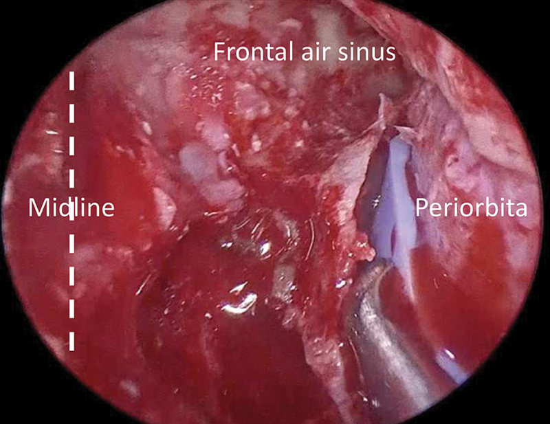
Intraoperative endoscopic endonasal view of the most lateral portion of the left frontal sinus after orbit “transposition.”
References
-
- Hayek G, Mercier P, Fournier H D. Anatomy of the orbit and its surgical approach. Adv Tech Stand Neurosurg. 2006;31(01):35–71. - PubMed
-
- Pai S B, Nagarjun M N. A neurosurgical perspective to approaches to the orbit: A cadaveric study. Neurol India. 2017;65(05):1094–1101. - PubMed
-
- Kirollos R, Helmy A, Thomson S, Hutchinson P. Oxford, United Kingdom: Oxford University Press; 2019. Oxford Textbook of Neurological Surgery. 1st ed; pp. 221–227.
-
- Graham S M, Thomas R D, Carter K D, Nerad J A. The transcaruncular approach to the medial orbital wall. Laryngoscope. 2002;112(06):986–989. - PubMed
