. 2020 Nov 25;11(1):5984.
doi: 10.1038/s41467-020-19811-9.

High-resolution sampling of beam-driven plasma wakefields

Affiliations

High-resolution sampling of beam-driven plasma wakefields

S Schröder et al. Nat Commun. .

Erratum in

  • Author Correction: High-resolution sampling of beam-driven plasma wakefields.
    Schröder S, Lindstrøm CA, Bohlen S, Boyle G, D'Arcy R, Diederichs S, Garland MJ, Gonzalez P, Knetsch A, Libov V, Niknejadi P, Põder K, Schaper L, Schmidt B, Sheeran B, Tauscher G, Wesch S, Zemella J, Zeng M, Osterhoff J. Schröder S, et al. Nat Commun. 2021 Jan 8;12(1):371. doi: 10.1038/s41467-020-20676-1. Nat Commun. 2021. PMID: 33420017 Free PMC article. No abstract available.

Abstract

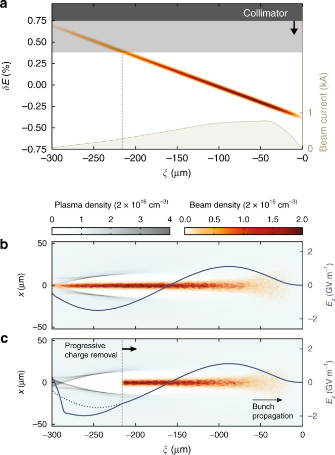
Plasma-wakefield accelerators driven by intense particle beams promise to significantly reduce the size of future high-energy facilities. Such applications require particle beams with a well-controlled energy spectrum, which necessitates detailed tailoring of the plasma wakefield. Precise measurements of the effective wakefield structure are therefore essential for optimising the acceleration process. Here we propose and demonstrate such a measurement technique that enables femtosecond-level (15 fs) sampling of longitudinal electric fields of order gigavolts-per-meter (0.8 GV m-1). This method-based on energy collimation of the incoming bunch-made it possible to investigate the effect of beam and plasma parameters on the beam-loaded longitudinally integrated plasma wakefield, showing good agreement with particle-in-cell simulations. These results open the door to high-quality operation of future plasma accelerators through precise control of the acceleration process.


Conflict of interest statement

The authors declare no competing interests.

Figures

Fig. 1
Fig. 1. Plasma wakefield sampling by energy collimation.
a A strongly correlated longitudinal phase space allows tail slices to be progressively removed from the bunch, e.g., by collimation in a dispersive section. b An electron bunch interacts with a plasma and excites a density wake with strong longitudinal electric fields (3D particle-in-cell simulation). c Removing charge from the bunch tail alters the wakefield (compared to the original field, dotted line), but does not alter the wakefield experienced by the remaining bunch charge. By subtracting the final energy spectrum of consecutive collimator steps, the energy change of each longitudinal slice can be determined—revealing the effective wakefield.
Fig. 2
Fig. 2. Experimental setup.
a An electron beam with a linearly chirped longitudinal phase space is characterised in a parallel beam line using a TDS. b A beam enters a dispersive section with energy collimators for optional removal of the tail (high energy), the head (low energy), and the centre (for two-bunch generation). The beam charge is measured with a toroid after collimation and before the beam is focused into a discharge plasma cell. c The relative time-of-arrival of the beam is adjusted to reach the desired plasma density: the temporal evolution of the average density was measured using two-colour interferometry in a test stand with a replica cell. d Finally, the beam following plasma interaction passes through a quadrupole triplet and is vertically dispersed by a spectrometer dipole to form a point-to-point image on a scintillating LANEX screen.
Fig. 3
Fig. 3. Evolution of the tail-collimated energy spectrum.
a As the tail collimator is moved in (horizontal axis), the tail particles are progressively removed from the plasma-interacted energy spectrum; 70 shots are collected per step. b The same scan is repeated with no plasma (20 shots per step), demonstrating the energy collimation of the incoming bunch. c The difference of (averaged) spectra at consecutive collimator steps reveals the energy of each slice of the plasma-interacted bunch. d By subtracting the plasma-off energy of each slice, the wakefield signal can be extracted.
Fig. 4
Fig. 4. Measured longitudinally averaged plasma wakefields.
a The wakefield of the nominal beam and plasma is sampled with a 6 μm granularity. Error bars represent the shot-to-shot standard deviation. The solid line shows the corresponding PIC simulated wakefield. b The measurement is repeated with the same beam current profile and an 80% higher plasma density (the beam arrives 1.7 μs earlier), producing a shorter wavelength wakefield. c At the nominal density (same as in a), the beam current is notch-collimated into a double-bunch profile, producing a wakefield which is identical at the head, but strongly altered at the tail. The end point of ξ = −240 μm is determined by signal-to-noise ratio.

References

    1. Tajima T, Dawson JM. Laser electron accelerator. Phys. Rev. Lett. 1979;4:267–270. doi: 10.1103/PhysRevLett.43.267. - DOI
    1. Joshi C, Katsouleas TC. Plasma accelerators at the energy frontier and on tabletops. Phys. Today. 2003;56:47–53. doi: 10.1063/1.1595054. - DOI
    1. Couprie ME, Loulergue A, Labat M, Lehe R, Malka V. Towards a free electron laser based on laser plasma accelerators. J. Phys. B. 2014;47:234001. doi: 10.1088/0953-4075/47/23/234001. - DOI
    1. Chen P, Dawson JM, Huff RW, Katsouleas T. Acceleration of electrons by the interaction of a bunched electron beam with a plasma. Phys. Rev. Lett. 1985;54:693–696. doi: 10.1103/PhysRevLett.54.693. - DOI - PubMed
    1. Ruth RD, Chao AW, Morton PL, Wilson PB. A plasma wake field accelerator. Part. Accel. 1985;17:171.