. 2020 Nov 24;11(12):1394.
doi: 10.3390/genes11121394.

Role of PB1 Midbody Remnant Creating Tethered Polar Bodies during Meiosis II

Affiliations

Role of PB1 Midbody Remnant Creating Tethered Polar Bodies during Meiosis II

Alex McDougall et al. Genes (Basel). .

Abstract

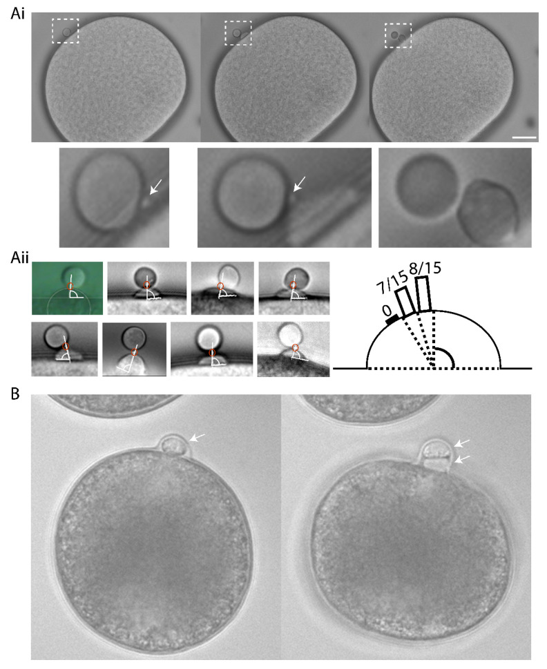
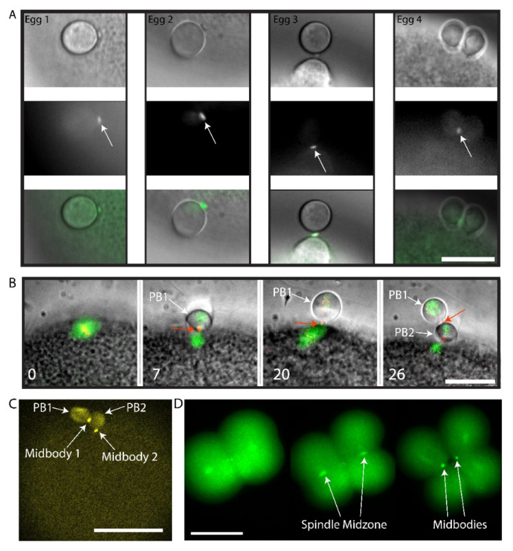
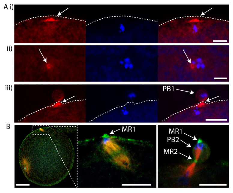
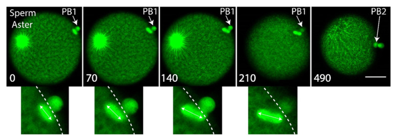
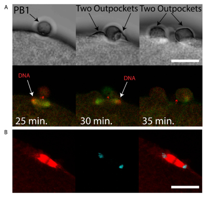
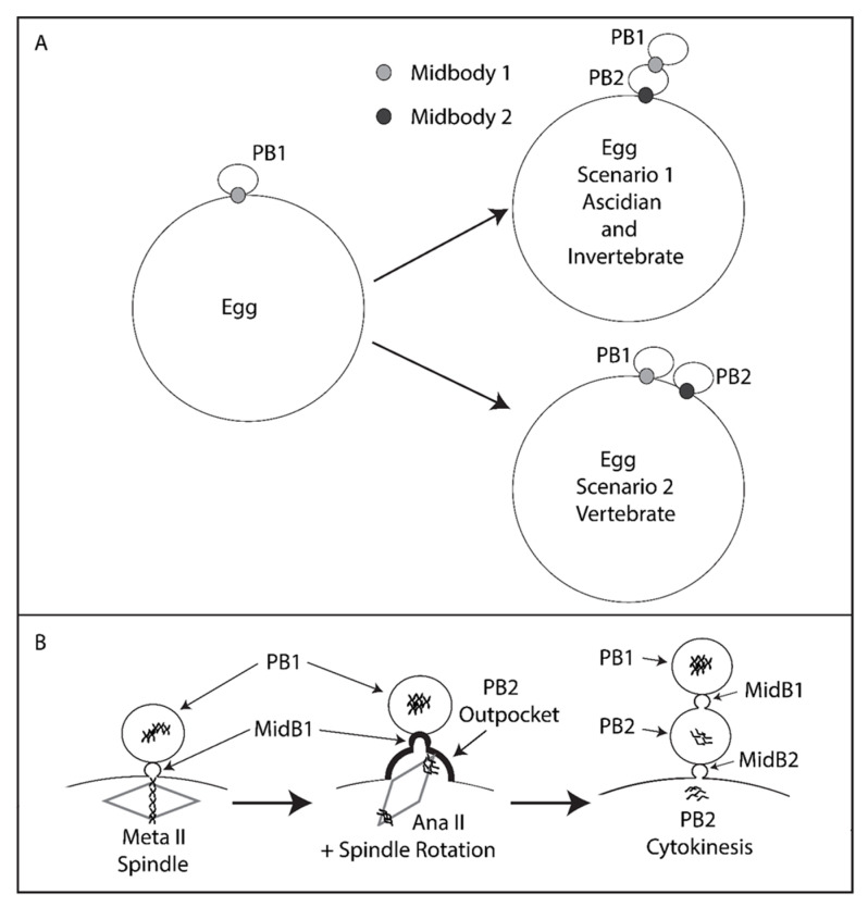
Polar body (PB) formation is an extreme form of unequal cell division that occurs in oocytes due to the eccentric position of the small meiotic spindle near the oocyte cortex. Prior to PB formation, a chromatin-centered process causes the cortex overlying the meiotic chromosomes to become polarized. This polarized cortical subdomain marks the site where a cortical protrusion or outpocket forms at the oocyte surface creating the future PBs. Using ascidians, we observed that PB1 becomes tethered to the fertilized egg via PB2, indicating that the site of PB1 cytokinesis directed the precise site for PB2 emission. We therefore studied whether the midbody remnant left behind following PB1 emission was involved, together with the egg chromatin, in defining the precise cortical site for PB2 emission. During outpocketing of PB2 in ascidians, we discovered that a small structure around 1 µm in diameter protruded from the cortical outpocket that will form the future PB2, which we define as the "polar corps". As emission of PB2 progressed, this small polar corps became localized between PB2 and PB1 and appeared to link PB2 to PB1. We tested the hypothesis that this small polar corps on the surface of the forming PB2 outpocket was the midbody remnant from the previous round of PB1 cytokinesis. We had previously discovered that Plk1::Ven labeled midbody remnants in ascidian embryos. We therefore used Plk1::Ven to follow the dynamics of the PB1 midbody remnant during meiosis II. Plk1::Ven strongly labeled the small polar corps that formed on the surface of the cortical outpocket that created PB2. Following emission of PB2, this polar corps was rich in Plk1::Ven and linked PB2 to PB1. By labelling actin (with TRITC-Phalloidin) we also demonstrated that actin accumulates at the midbody remnant and also forms a cortical cap around the midbody remnant in meiosis II that prefigured the precise site of cortical outpocketing during PB2 emission. Phalloidin staining of actin and immunolabelling of anti-phospho aPKC during meiosis II in fertilized eggs that had PB1 removed suggested that the midbody remnant remained within the fertilized egg following emission of PB1. Dynamic imaging of microtubules labelled with Ens::3GFP, MAP7::GFP or EB3::3GFP showed that one pole of the second meiotic spindle was located near the midbody remnant while the other pole rotated away from the cortex during outpocketing. Finally, we report that failure of the second meiotic spindle to rotate can lead to the formation of two cortical outpockets at anaphase II, one above each set of chromatids. It is not known whether the midbody remnant of PB1 is involved in directing the precise location of PB2 since our data are correlative in ascidians. However, a review of the literature indicates that PB1 is tethered to the egg surface via PB2 in several species including members of the cnidarians, lophotrochozoa and echinoids, suggesting that the midbody remnant formed during PB1 emission may be involved in directing the precise site of PB2 emission throughout the invertebrates.

Keywords: ascidian; meiotic spindle; midbody remnant; second polar body.


Conflict of interest statement

The authors declare no competing financial interest.

Figures

Figure 1
Figure 1
A small protrusion forms on the surface of the PB2 outpocket in Phallusia. (Ai) Bright field images from a time-lapse experiment of fertilized Phallusia mammillata eggs. During polar body 2 (PB2) emission, a small polar corps can be observed on the surface of PB2 outpocket (boxed region). Enlarged views of the boxed regions at the bottom show in greater detail the small protrusion which is present before outpocketing begins (bottom left, arrow) and remains present during outpocketing (bottom middle, arrow). n > 50 eggs. Scale bar = 20 µm. See Supplementary Movie S1. (Aii) Analysis of angle between polar corps (red circle) and outpocket center. Diagram illustrating a summary of the polar corps position at 61–70°, 71–80° and 81–90° (number of eggs in brackets). Mean polar corps position was 81.4°+/−1.4° +/−sem, n = 15. (B) Bright field images from a time-lapse experiment showing PB2 emission under PB1 in Mytilus galloprovincialis. PB1 is indicated by the arrow in the first image, and both PB1 and PB2 by the two arrows in the second image. n = 50/50. See Supplementary Movie S2.
Figure 2
Figure 2
Plk1::Venus labels the midbody that forms between PB1 and the egg. (A) Four different examples of the small polar corps labelled with Plk1::Ven. Upper row of images shows bright field images of PB2 emission site adjacent to PB1. Middle row of images shows that Plk1::Ven labelled the midbody that formed between PB1 and the egg (see arrows). Bottom row is the overlay. Plk1::Ven localization to the midbody during the process of PB2 emission (see arrows). n = 12/12. Scale bar = 20 µm. (B) Epifluorescence images of meiotic spindle labelled with EB3::3GFP and the midbody with Plk1::Rfp1. Please note that Plk1::Rfp1 labels the chromosomes (red) on the Meta I spindle (first image), then the midbody (second image) and also that the midbody is found at the apex of the PB2 outpocket (third image). PB1 is tethered to PB2 (fourth image). First midbody is indicated with red arrows and PBs are indicated by the white arrows. Time in minutes is indicated. Scale bar = 20 µm. n = 5/5 from time-lapse experiments. (C) Fertilized egg after PB1 and PB2 emission. One confocal plane from a z-stack showing the localization of Plk1::Ven to midbody 1 and midbody 2 (arrows). PB1 and PB2 are also indicated by arrows. n = 12/12. Scale bar = 50µm. See Supplementary Movie S3. (D) Two to four cell-stage. Epifluorescence images of midbody formation. Plk1::Ven labels the central spindle (arrows) then both midbodies (arrows) at the end of cytokinesis. n = 22. Scale bar = 50 µm.
Figure 3
Figure 3
First midbody remains associated with the fertilized egg following PB1 emission. (A) Fertilized eggs were fixed during meiosis II and stained using Phalloidin::TRITC to label actin and Hoechst to label chromosomes. (i) Confocal images showing actin cap (arrows) during meiosis II in an egg following PB1 removal. (ii) Confocal images showing actin labelling of the midbody (arrows) during meiosis II in an egg following PB1 removal (arrows). (iii) Control egg that displayed PB1 attached to the egg surface. Please note that the midbody is strongly labelled with Phalloidin (arrows). Dotted line indicates surface of the egg. Scale bars = 10 µm. n > 50 for (i) and (ii) where Phalloidin labelled the actin cap (i) and midbody (ii). n > 50 for Phalloidin labelling of outpocket (iii). (B) Fertilized eggs were pipetted during meiosis II to remove PB1, fixed and labelled with anti-phospho aPKC (green), anti-tubulin (red) and DAPI (blue). Left image: overlay showing the rotated second meiotic spindle. The sperm aster is also visible, far left. Scale bar = 30µm. Middle image: inset of boxed region showing that one pole of second meiotic spindle is aligned with PB1 midbody remnant (MR1 arrow). Please note that PB1 was removed by pipetting. Scale bar = 10µm. Right image: Another fertilized egg which had already emitted PB2 showing location of first midbody remnant (MR1, arrows), second midbody remnant (MR2, arrow) and PB2 (arrow). Please note that PB1 was removed by pipetting. n > 50 zygotes where aPKC labelled the midbody remnant. Scale bar = 10µm. Also see Supplementary Movies S4 and S5 of LifeAct labelling.
Figure 4
Figure 4
Second meiotic spindle rotates during PB2 emission. Eggs were previously microinjected with mRNA encoding Ens::3GFP to label the microtubules (green). Confocal images extracted from a time-lapse experiment showing the rotation of the second meiotic spindle. Upper row of images showing that the second meiotic spindle lies under PB1 parallel to the cortical surface, then begins to rotate (image 2) and continues to rotate (images 3 and 4) as PB2 is emitted (see last image of Figure and of Supplementary Movie S6). The meiotic spindle rotates 50°+/− 3°, n = 13, mean +/− sem. Insets at the bottom show more clearly the rotation of the second meiotic spindle (double headed arrow shows spindle orientation). Large sperm aster is also visible. n = 13. Scale bar = 40 µm. Time between images is indicated in seconds on each image. See Supplementary Movie S6.
Figure 5
Figure 5
Failed rotation of second meiotic spindle giving two PB2 outpockets. (A) Unfertilized eggs were injected with mRNAs encoding Ens::3GFP (microtubules green) and Kif2::mCherry (chromosomes red) mRNA. Two outpockets are shown in the second and third bright field images respectively (arrows). Please note that the second meiotic spindle fails to rotate and two outpockets form above both sets of chromosomes following Ana II (see 24–31 min. on Supplementary Movie S8). Note also that Kif2::mCherry also labels the midbody (prominent red staining near PB1). Scale bar = 20 µm. n = 5/5 examples of parallel spindles. See Supplementary Movie S8 for the full data-set. Another example of two simultaneous PB2 outpockets is shown in Supplementary Movie S7. (B) Fertilized eggs were fixed and labelled with anti-Tubulin (red) and stained with DAPI (blue). Confocal images of a spindle positioned parallel to the egg cortex in anaphase. Scale bar = 20 µm, n = 5 examples of parallel MII spindles.
Figure 6
Figure 6
Model. Tethered polar bodies. (A) Scenario 1: tethered polar bodies. Following emission of both polar bodies, the first midbody attaches PB1 to PB2 while the second midbody links PB2 to the egg. PB1 is thus tethered to the egg indirectly via PB2. Scenario 1 represents ascidians and possibly many invertebrates (see Table 1 for details). Scenario 2: the first midbody links PB1 to the egg and the second midbody also links PB2 to the egg. Scenario 2 represents mouse and Xenopus. Midbody 1 is depicted as light grey, midbody 2 as dark grey. However, it should be stressed that midbody position is only known for certainty in the ascidian (this study). (B) PB2 emission dynamics. Midbody 1 is located at the apex of PB2 cortical outpocket. Spindle rotation into PB2 cortical outpocket is displayed. PB2 is emitted attached to PB1 via midbody 1 (MidB1) and PB1 is thus tethered indirectly to the egg via PB2.

References

    1. Azoury J., Lee K.W., Georget V., Rassinier P., Leader B., Verlhac M.-H. Spindle Positioning in Mouse Oocytes Relies on a Dynamic Meshwork of Actin Filaments. Curr. Biol. 2008;18:1514–1519. doi: 10.1016/j.cub.2008.08.044. - DOI - PubMed
    1. Prodon F., Chenevert J., Sardet C. Establishment of animal–vegetal polarity during maturation in ascidian oocytes. Dev. Biol. 2006;290:297–311. doi: 10.1016/j.ydbio.2005.11.025. - DOI - PubMed
    1. Schuh M., Ellenberg J. A New Model for Asymmetric Spindle Positioning in Mouse Oocytes. Curr. Biol. 2008;18:1986–1992. doi: 10.1016/j.cub.2008.11.022. - DOI - PubMed
    1. Eager D.D., Johnson M.H., Thurley K.W. Ultrastructural studies on the surface membrane of the mouse egg. J. Cell Sci. 1976;22:345–353. - PubMed
    1. Maro B., Johnson M.H., Pickering S.J., Flach G. Changes in actin distribution during fertilization of the mouse egg. J. Embryol. Exp. Morphol. 1984;81:211–237. - PubMed

Publication types

MeSH terms