Review
. 2020 Nov 25;25(23):5510.
doi: 10.3390/molecules25235510.

Recent Advances in The Polymer Dispersed Liquid Crystal Composite and Its Applications

Affiliations
Review

Recent Advances in The Polymer Dispersed Liquid Crystal Composite and Its Applications

Mohsin Hassan Saeed et al. Molecules. .

Abstract

Polymer dispersed liquid crystals (PDLCs) have kindled a spark of interest because of their unique characteristic of electrically controlled switching. However, some issues including high operating voltage, low contrast ratio and poor mechanical properties are hindering their practical applications. To overcome these drawbacks, some measures were taken such as molecular structure optimization of the monomers and liquid crystals, modification of PDLC and doping of nanoparticles and dyes. This review aims at detailing the recent advances in the process, preparations and applications of PDLCs over the past six years.

Keywords: applications; doping; polymer-dispersed liquid crystals; polymerization induced phase separation.


Conflict of interest statement

The authors declare no conflict of interest.

Figures

Figure 1
Figure 1
Operating principle of a common polymer dispersed liquid crystal (PDLC) device. (a) off-state, (b) on-state.
Figure 2
Figure 2
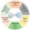
An illustration of the preparation, electro-optical properties optimization and applications of PDLC.
Figure 3
Figure 3
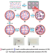
Schematic illustration of the preparation of polymer dispersed and polymer stabilized liquid crystal (PD&PSLC) composite film. (a) Homogeneous isotropic mixture sandwiched between two pieces of plastic sheets. (b) Microphase separation between the liquid crystalline mixture and polymer matrix. (c) Randomly oriented liquid crystalline mixture within a liquid crystal (LC) droplet. (d) Perpendicularly aligned liquid crystalline mixture. (e) Homeotropically aligned polymer network (HAPN) formed within an LC droplet. (f) The N* phase gradually turns into the SmA phase upon the consumption of photopolymerizable monomers. (g) Perpendicularly aligned SmA phase within an LC droplet. (h) Focal-conic texture of the heat-induced N* phase within an LC droplet. (i) Photograph of the transparent state of the film at a temperature below the phase-transition temperature of the LC. (j) Photograph of the heat-induced light-scattering state of the film. Reproduced with permission from ref. [66]. Copyright 2017, ACS Publication.
Figure 4
Figure 4
Scanning electron microscope (SEM) photographs of the polymer networks of the films observed from a side view of the cells. (a) A porous structure of polymer networks of PDLC composite film. (b) The HAPN of PSLC composite film. (c) A coexistent structure of both the porous polymer networks and the HAPN of PD&PSLC composite film. Reproduced with permission from ref. [66]. Copyright 2017, ACS Publications.
Figure 5
Figure 5
Graphical representations of LC droplets size of images observed by POM with 50× magnification taken during the experiment (a) bipolar and radial configuration of LC droplets and (be) stable bipolar configuration with respect to their diverse size of LC droplets with dye concentration. Reproduced with permission from ref. [97]. Copyright 2017, ELSEVIER Publications. SEM images of (f) pure PDLC, (g) PDLC + 1% MR, (h) PDLC + 3% MR and (i) PDLC + 5% MR composites. Reproduced with permission from ref. [87]. Copyright 2019, ELSEVIER Publications.
Figure 6
Figure 6
Schematic illustration of the preparation of crosslinked V-LCs/polymer composite films. (a) The homogeneous polymeric syrup containing quantum dots sandwiched between two conductive ITO glass substrates coating with PVA. (b) The PDVLC film was formed by the first step radical polymerization of weak UV light to initiate microphase between V-LCs and polymer matrix. (c) Enlarged V-LCs domains with randomly oriented liquid crystal mixture. (d) V-LCs were homeotropically aligned when the electrical field was applied. (e) The second step cationic polymerization of intense UV light was carried out to prepare the PDCVLC by the polymerization of V-LC monomers. (f) Enlarged V-LCs domains with the polymerization of V-LC monomers. (g) The F-PDCVLC film was developed by introducing the perfluoro acrylate monomers into the original syrup and repeating the above dual-step polymerization. (h) Enlarged polymer matrix with the perfluoro acrylate monomers. Reproduced with permission from ref. [8]. Copyright 2019, ELSEVIER Publications.
Figure 7
Figure 7
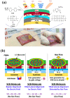
Structure and basic device performances of flexible PDLC-i-OFETs. (a) Illustration for the device structure and materials used in this work (photographs demonstrate attachment of flexible PDLC-i-OFET array sensors on human hands), (b) Sensing performance by weak gas flow stimulations and mechanism change of 5CB alignment in the channel region of PDLC-i-OFET devices according to applied voltages and nitrogen gas stimulations: illustrations for possible orientation of 5CB molecules in the LC micro-dots in the channel layers. Reproduced with permission from ref. [133] Copyright 2017, Springer Nature Publications.
Figure 8
Figure 8
(a) Schematic representation and working principle of PDLC-coupled LSC [138] (b) Schematic exploded representations of an active LSC window containing red-NIR phosphorescent octahedral molybdenum nanoclusters composed of a PDLC matrix containing the phosphorescent inorganic emitter surrounded by PV cells on its edges [138]. Figure 8a,b reproduced with permission from Ref. [138] Copyright 2017, ACS Publications (c) PDLC backside emissions of an N-CQDs-based waveguide coupled with no PDLC and with PDLC. The driving voltage in the ON state was kept constant at 50 V (d) Backside emission power of PDLC-LSC devices in the OFF and ON mode. The driving voltage in the ON mode was kept constant at 50 V in both devices. (e) Color possibilities of transmitted light through the ON and OFF states of a waveguide-coupled PDLC device plotted on a CIE 1931 XY chromaticity diagram. Figure 8c–e reproduced with permission from Ref. [134,136]. Copyright 2019, ELSEVIER Publications.

Similar articles

Cited by

References

    1. Zhong T., Mandle R.J., Goodby J.W., Zhang L., Zhang C. Comparative studies of polymer-dispersed liquid crystal films via a thiol-ene click reaction. Polym. Adv. Technol. 2019;30:2781–2789. doi: 10.1002/pat.4710. - DOI
    1. Shen W., Wang L., Zhong T., Chen G., Li C., Chen M., Zhang C., Zhang L., Li K., Yang Z., et al. Electrically switchable light transmittance of epoxy-mercaptan polymer/nematic liquid crystal composites with controllable microstructures. Polymer. 2019;160:53–64. doi: 10.1016/j.polymer.2018.11.022. - DOI
    1. Hu G., Chen H., Liu Z., Zhang S., Zhou Y., Zhu B., Gu H. Tailoring structure and properties of polymer-dispersed liquid crystal by quenching process. Liq. Cryst. 2020;46:1–9. doi: 10.1080/02678292.2020.1750070. - DOI
    1. Li C., Chen M., Shen W., Chen G., Zhang L., Yang H. A study on the polymer structures and electro-optical properties of epoxy-mercaptan-based polymer dispersed liquid crystal films. Liq. Cryst. 2019;46:1718–1726. doi: 10.1080/02678292.2019.1595759. - DOI
    1. Ghosh A., Sundaram S., Mallick T.K., Mallick T.K. Evaluation of thermal performance for a smart switchable adaptive polymer dispersed liquid crystal (PDLC) glazing. Sol. Energy. 2020;195:185–193. doi: 10.1016/j.solener.2019.11.024. - DOI

LinkOut - more resources