. 2019 May 14;21(5):493.
doi: 10.3390/e21050493.

Informational Structures and Informational Fields as a Prototype for the Description of Postulates of the Integrated Information Theory

Affiliations

Informational Structures and Informational Fields as a Prototype for the Description of Postulates of the Integrated Information Theory

Piotr Kalita et al. Entropy (Basel). .

Abstract

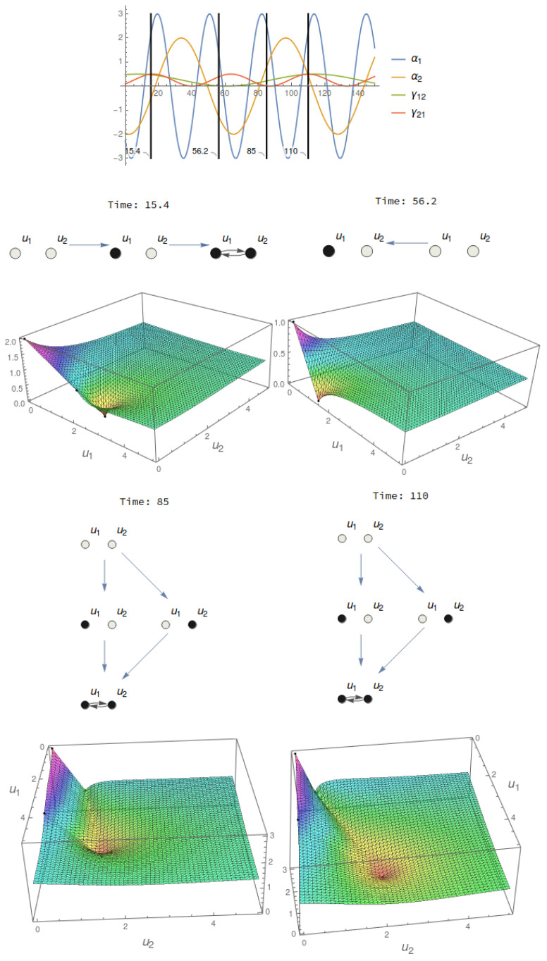
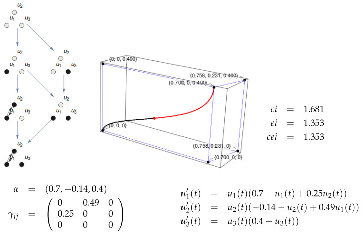
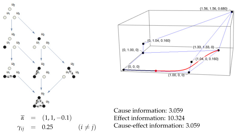
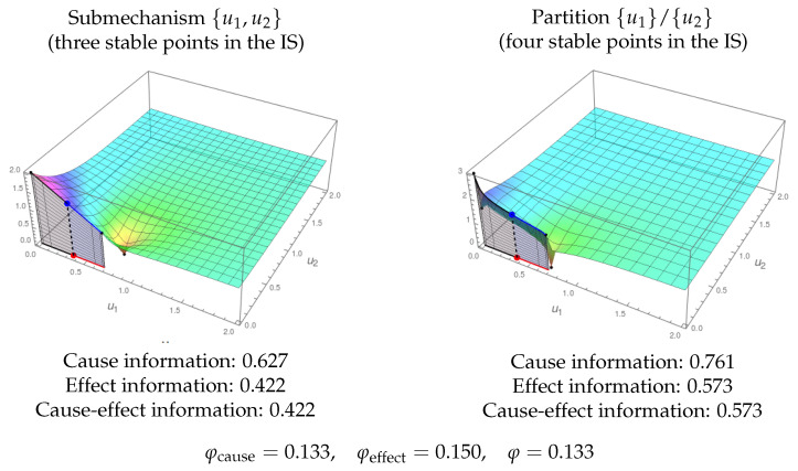
Informational Structures (IS) and Informational Fields (IF) have been recently introduced to deal with a continuous dynamical systems-based approach to Integrated Information Theory (IIT). IS and IF contain all the geometrical and topological constraints in the phase space. This allows one to characterize all the past and future dynamical scenarios for a system in any particular state. In this paper, we develop further steps in this direction, describing a proper continuous framework for an abstract formulation, which could serve as a prototype of the IIT postulates.

Keywords: Lotka–Volterra equations; dynamical system; global attractors; informational field; informational structure; integrated information theory.


Conflict of interest statement

The authors declare no conflict of interest. The funders had no role in the design of the study; the writing of the manuscript, or in the decision to publish the results.

Figures

Figure 1
Figure 1
The dynamics on a substrate with two nodes (top left) produces an Informational Structure (IS) and Informational Field (IF). In the example, α1=1.3, α2=1.4, γ12=0.1, γ21=0.2. The dynamics of the substrate is given by a system of differential equations (top right). The IS (bottom left) contains the stationary points and relations among them. The IF (bottom right) enriches the phase space with the Lyapunov functional. In the example, the point (0.8,0.9) in the phase space (red point) is associated with a certain level in the IF (blue point).
Figure 2
Figure 2
Informational structure of a three-node substrate with the given values of parameters α and γ. In the right figure, the stationary points are shown in the phase space. The blue lines represent solutions joining two stationary points, which belong to different energy levels. Two points are linked if there exists a complete solution converging to the past towards the first one and towards the other point for the future.
Figure 3
Figure 3
Dynamical IS and IF. Top: Temporal evolution of the parameters α and γ of a two-node mechanism. Bottom: ISs and IFs at four different instants. Observe that the third and fourth have the same structure, but given that the parameters are different, the shape of the IF changes. This fact will affect the informational measures of a state in the phase space.
Figure 4
Figure 4
Metastability. Left: the IF of a two-node system is shown with the past (black shadow) and future (blue) trajectories of a point close to the X-axis. The trajectory finishes in the global stationary point, but it flows for a long time around the semi-stable stationary point in the X-axis. The right figure represents the phase space and the points in the IS of a three-node mechanism. The trajectories of three different points to the past and future are shown. The states are (0.5,103,106) for the red point and trajectories, (103,0.5,103) for the green and (0.3,0.3,0.3) for the brown one. Red and green solutions show two phenomena of metastability associated with different paths for saddle stationary points, one in the X-axis and the other in the Y-axis.
Figure 5
Figure 5
Existence and composition of a two-node mechanism {u1,u2} in a state. The parameters are: α1=3, α2=2, γ12=0.4, γ21=0.3. Top left: Informational structure with the four stable points of the system: (0,0), (3,0), (0,2), and (4.09,3.64). Top right: Informational field. The black points correspond to the points in the IS. The system is in state (0.5,1.5). The red point represents the state in the phase space, and the blue one is its projection in the IF. Bottom: Informational fields of the submechanisms {u1} (left) and {u2} (right) of the original mechanism. With one node only, the phase space has one coordinate, and the blue lines represent the corresponding informational fields. The state of the system in each of the submechanisms is shown. Observe that in the equation for the submechanism {u1} (left, below its IF), the variable u2(t) is replaced by the constant 1.5 with the value of u2 in the given state of the system. It happens analogously in the case of the submechanism {u2}.
Figure 6
Figure 6
Cause-effect information of the system in Figure 5 also in state (0.5,1.5). The black area corresponds to the integral for the cause information, and the blue one is for effect information. The cause-effect information is the minimum of both values.
Figure 7
Figure 7
Effect information in the stable point (0,0). The IF represented in both figures corresponds to the two-node mechanism in Figure 5. In the left side, the path that passes through the point (3,0) is considered. The effect information that corresponds to that path (blue area) is 9.69. In the right side, the path passes through (0,2), and the value of the blue area is 8.22. Then, the effect information of this mechanism in the state (0,0) is 9.69 as it is the greatest integral of the possible paths moving from (0,0) to the global stable point (4.09,3.64).
Figure 8
Figure 8
Existence and information of a three-node mechanism in state (0.36,0,0.16). Top Left: Informational structure of the system corresponding to the α¯ and γij parameters below. Top right: Phase space with the nodes of the IS in black. The red point is the state of the system, and the black and red lines are the trajectories in the phase space for ci and ei, respectively. The IF cannot be represented as it lies in R4, but the value of the Lyapunov function in each point can be calculated (it is 3.47 for the current state). Bottom: Parameters of the mechanism and differential equations of the system. It can be observed that u1 and u2 have a mutual dependence, while u3 is not related to the other variables. As a consequence, the system has no integration as the partition {u1,u2}/{u3} produces the same IS and IF as the original mechanism.
Figure 9
Figure 9
Cause-effect information in a mechanism {u1,u2} and the partition {u1}/{u2}. In both cases, the state is (1,2). The left IF corresponds to the mechanism in Figure 5. There is no integration as the IS of the partition has the same structure. The equations to build the IS and IF of the partition are those depicted in Figure 5 (bottom), but one and two are used instead of 0.5 and 1.5 as the constant values for the variables outside each subsystem.
Figure 10
Figure 10
Existence and information of a three-node substrate. The IS is shown at the left. It corresponds to a three-node substrate with α1=α2=1, α3=0.1, and γij=0.25 for all connections between different nodes. At the right, the nodes of the IS are shown in the phase space together with the past (black line) and future (red line) solutions for the state (0.5,0.01,0). The projections in the IF cannot be shown as the IF lies in R4, but the integrals can be calculated. The values for ci, ei, and cei are shown.
Figure 11
Figure 11
Integration of the system in Figure 10. The informational structure of the partition {u1,u2}/{u3} is shown in the left. It is the one with both most similar ci and ei values to those of the original system. The integration φ is the minimum of φcause and φeffect, which are the (absolute value of the) differences between cause information and effect information in the original system and the partition.
Figure 12
Figure 12
Integration and exclusion. Left: IF corresponding to the submechanism given by the nodes {u1,u2} of the substrate in Figure 8 (with nodes {u1,u2,u3}). It is in state (0.36,0) (the original state was (0.36,0,0.16)). Cause and effect information is shown. Right: IF of the partition {u1}/{u2} in the same sate. Given that the structure of the ISs is different for {u1,u2} (three nodes) and {u1}/{u2} (four nodes), the substrate is integrating information. Recall that the original substrate does not integrate information as u3 is disconnected from u1 and u2 (Figure 8). As this submechanism from {u1,u2} is the one integrating more information, the exclusion postulate determines that this is the one contributing to the conscious experience.
Figure 13
Figure 13
Exclusion. The submechanism given by {u1,u3} of the system in Figure 10 in state (0.5,0) has integrated information, φ=0.144. In the figure, both the IF for the submechanism {u1,u3} (left) and for the partition {u1}/{u3} (right) are shown. However, as the integrated information is lower than that of the complete system (Figure 11, φ=0.243), the exclusion postulate chooses the whole substrate {u1,u2,u3} as the one producing more integrated information.

Similar articles

Cited by

References

    1. Deco G., Jirsa V. Ongoing cortical activity at rest: Criticality, multistability, and ghost attractors. J. Neurosci. 2012;32:3366–3375. doi: 10.1523/JNEUROSCI.2523-11.2012. - DOI - PMC - PubMed
    1. Ghosh A., Rho Y., McIntosh A., Kotter R., Jirsa V. Cortical network dynamics with time delays reveals functional connectivity in the resting brain. Cogn. Neurodyn. 2008;2:115–120. doi: 10.1007/s11571-008-9044-2. - DOI - PMC - PubMed
    1. Deco G., Tononi G., Boly M., Kringelbach M. Rethinking segregation and integration: Contributions of whole-brain modelling. Nat. Rev. Neurosci. 2015;16:430–439. doi: 10.1038/nrn3963. - DOI - PubMed
    1. Honey C., Kotter R., Breakspear M., Sporns O. Network structure of cerebral cortex shapes functional connectivity on multiple time scales. Proc. Natl. Acad. Sci. USA. 2007;104:10240–10245. doi: 10.1073/pnas.0701519104. - DOI - PMC - PubMed
    1. Rabinovich M., Varona P., Tristan I., Afraimovich V. Chunking dynamics: Heteroclinics in mind. Front. Comput. Neurosci. 2014;8:1–10. doi: 10.3389/fncom.2014.00022. - DOI - PMC - PubMed

LinkOut - more resources