. 2020 Dec 4;10(1):21293.
doi: 10.1038/s41598-020-77986-z.

Voltage and pH difference across the membrane control the S4 voltage-sensor motion of the Hv1 proton channel

Affiliations

Voltage and pH difference across the membrane control the S4 voltage-sensor motion of the Hv1 proton channel

T Moritz Schladt et al. Sci Rep. .

Abstract

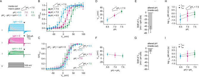
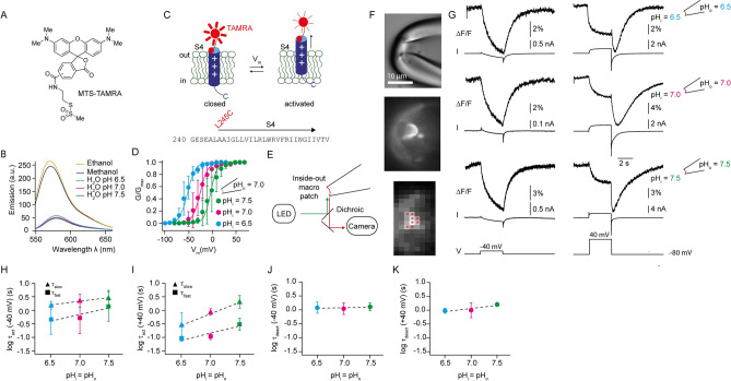
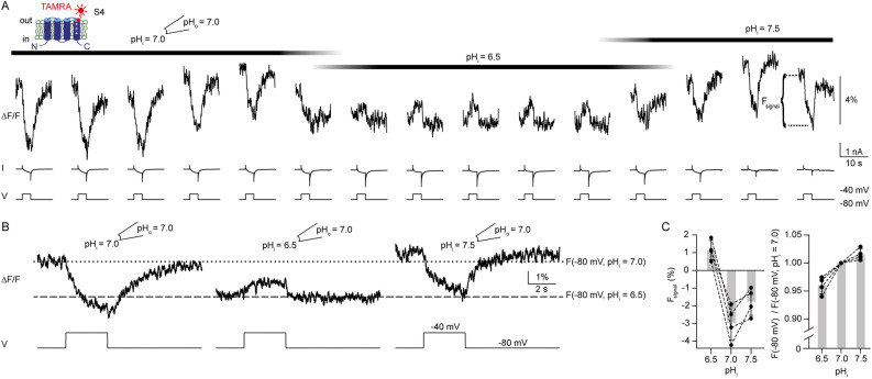
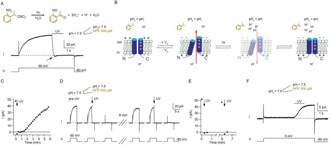
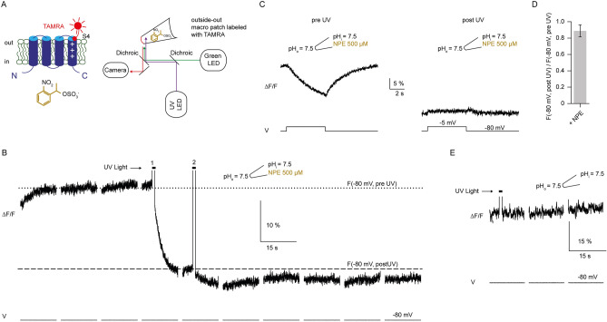
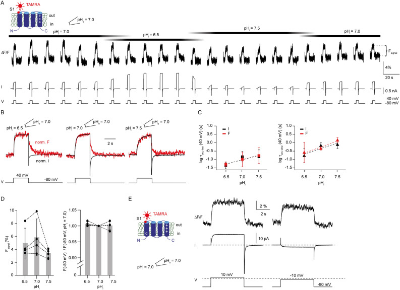
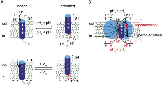
The voltage-gated proton channel Hv1 is expressed in a variety of cells, including macrophages, sperm, and lung epithelial cells. Hv1 is gated by both the membrane potential and the difference between the intra- and extracellular pH (ΔpH). The coupling of voltage- and ∆pH-sensing is such that Hv1 opens only when the electrochemical proton gradient is outwardly directed. However, the molecular mechanism of this coupling is not known. Here, we investigate the coupling between voltage- and ΔpH-sensing of Ciona intestinalis proton channel (ciHv1) using patch-clamp fluorometry (PCF) and proton uncaging. We show that changes in ΔpH can induce conformational changes of the S4 voltage sensor. Our results are consistent with the idea that S4 can detect both voltage and ΔpH.


Conflict of interest statement

The authors declare no competing interests.

Figures

Figure 1
Figure 1
Voltage dependence of ciHv1 is coupled to the difference between pHi and pHo (∆pH), but not to pH itself. (A) inside-out patch-clamp recordings of ciHv1 at different ∆pH conditions. (B) Mean GVs derived from tail currents (at time points specified by triangles in panel A) at different ∆pH conditions. Data from individual patches were fitted with Boltzmann functions (not shown), and the resulting mean slopes and mean V1/2 values were used to construct Boltzmann fits for the mean GVs (see Table 1 for fit parameters). (C) GVs derived from tail currents of inside-out patch-clamp recordings of ciHv1 at different pH, leaving ∆pH = 0, fitted with Boltzmann functions. (D) V1/2 as a function of pHi while pHo = 7. The dashed line is a linear fit with a slope of − 48.6 mV/∆pH unit; r2 = 0.8, p < 0.05. (E) shift of V1/2 per ∆pH unit (altered pHi, − 48.6 ± 9.5 mV). (F) V1/2 as a function of the pH itself. The dashed line is a linear fit with a slope of − 9.1 mV/pH unit; r2 = 0.1, n.s. (G), shift of V1/2 per pH unit (− 9.1 ± 4.6 mV). (H) activation time constants τfast and τslow as function of pHi while pHo = 7 (see also Table 2). The dashed lines are linear fits with slope(τfast) =  − 0.8 log(s)/ΔpH unit, r2 = 0.3, p < 0.05, and slope(τslow) =  − 0.6 log(s)/ΔpH unit, r2 = 0.4, p < 0.05. (I), activation time constants τfast and τslow as function of pH (∆pH = 0, see also Table 2). The dashed lines are linear fits with slope(τfast) = 0.3 log(s)/pH unit, r2 = 0.2, p < 0.05, and slope(τslow) = 0.4 log(s)/pH unit, r2 = 0.3, p < 0.05. Error bars indicate the SD.
Figure 2
Figure 2
PCF recordings at the extracellular end of S4 for different symmetric pH conditions. (A) chemical structure of MTS-TAMRA. (B) emission spectrum of MTS-TAMRA (50 nM) in ethanol, methanol, and aqueous solutions buffered to various pH values. Excitation wavelength was 542 nm. (C) top, cartoon depicting voltage-evoked S4 conformational change of ciHv1-L245C-TAMRA. For clarity, only S4 is shown. “ + ” signs denote the charged arginines in S4. Bottom, amino-acid sequence of the S4 voltage sensor of ciHv1 and the site of labeling. (D) GVs derived from tail currents of inside-out patch-clamp recordings of ciHv1-L245C-TAMRA at different ∆pH conditions, fitted with Boltzmann functions (see Table 1 for fit parameters). (E) scheme of the inside-out PCF recording condition. (F) excised inside-out patch containing ciHv1-L245C-TAMRA (top, bright-field image; middle, epifluorescent image; bottom, 8 × 8-binned epifluorescent image). Red stars mark pixels included in analysis. (G) representative inside-out PCF recordings of ciHv1-245C-TAMRA, in response to voltage steps from − 80 to − 40 (left) or + 40 mV (right) at different pH conditions leaving ∆pH = 0. The fluorescence (∆F/F) is the spatial average of the pixel intensities of the marked pixels as exemplified in panel F (bottom, see Methods). (HI), mean activation time constants τfast and τslow of Fsignal at − 40 mV (panel H) or + 40 mV (panel I) as a function of pH (see also Table 3). The dashed lines are linear fits with the following slopes: slope(τfast) = 0.5 log(s)/pH unit, r2 = 0.2, n.s., and slope(τslow) = 0.3 log(s)/pH unit, r2 = 0.1, n.s., at − 40 mV; slope(τfast) = 0.5 log(s)/pH unit, r2 = 0.6, p < 0.05 and slope(τslow) = 0.9 log(s)/pH unit, r2 = 0.5, p < 0.05, at + 40 mV. (JK) mean deactivation time constants τdeact of FSignal during repolarization from − 40 mV (panel J) or + 40 mV (panel K) to − 80 mV as function of pH (see also Table 3). The dashed lines are linear fits with the following slopes: slope(τdeact) = 0.03 log(s)/pH unit, r2 = 0.005, n.s., for − 40 mV; slope(τdeact) = 0.2 log(s)/pH unit, r2 = 0.3, n.s., for + 40 mV. Error bars indicate the SD.
Figure 3
Figure 3
Changes in ∆pH induce S4 conformational changes. (A) representative inside-out PCF recording of ciHv1-L245C-TAMRA in response to repetitive voltage steps from − 80 mV to − 40 mV and back while changing pHi and keeping pHo = 7.0. The voltage-evoked fluorescence signal is denoted as Fsignal. (B) mean fluorescence signals calculated from (A) for different pHi while pHo = 7.0. Horizontal lines (dotted, pHi = 7.0; dashed, pHi = 6.5) indicate the average fluorescence at − 80 mV. (C) left, amplitude of Fsignal as a function of pHi while pHo = 7.0 (n = 4 patches from 4 different cells). For pHi = 6.5, Fsignal = 1.1 ± 0.5; for pHi = 7.0, Fsignal =  − 3.0 ± 1.0; for pHi = 7.5, Fsignal =  − 1.8 ± 0.8; one-way ANOVA, p < 0.001; post-hoc analysis: Fsignal for pHi = 7.0 vs. Fsignal for pHi = 6.5: p = 0.0001; Fsignal for pHi = 7.0 vs. Fsignal for pHi = 7.5: p = 0.1; Fsignal for pHi = 6.5 vs. Fsignal for pHi = 7.5: p = 0.002). Right, baseline fluorescence at − 80 mV (F(− 80 mV)) as a function of pHi while pHo = 7.0, normalized to F(− 80 mV) at pHi = 7.0 (n = 4 patches from 4 different cells). For pHi = 6.5, F(− 80 mV) = 0.96 ± 0.02; for pHi = 7.5, F(− 80 mV) = 1.02 ± 0.01; one-way ANOVA: p < 0.001; post-hoc analysis: F(− 80 mV) for pHi = 7.0 vs. F(− 80 mV) for pHi = 6.5, p = 0.001; F(− 80 mV) for pHi = 7.0 vs. F(− 80 mV) for pHi = 7.5, p = 0.15; F(− 80 mV) for pHi = 6.5 vs. F(− 80 mV) for pHi = 7.5, p < 0.001. Error bars indicate the SD.
Figure 4
Figure 4
Proton uncaging rapidly and transiently acidifies the pipette solution at the membrane patch. (A) top, chemical structure and uncaging reaction of NPE-caged-proton. Bottom, representative inside-out patch-clamp recording of ciHv1 in response to a voltage step from − 60 mV to + 60 mV. UV light was applied for 1 s. The patch pipette contained 500 µM NPE-caged-proton buffered to pHo = 7.5 with 0.1 mM HEPES, while the bath solution was buffered to pHi = 7.5 with 100 mM HEPES. (B) gating scheme of ciHv1. For clarity, only S1 and S4 are shown. “ + ” signs denote the charged arginines in S4. Red arrows indicate the direction of proton current. (C) current amplitude of an inside-out patch-clamp recording in response to repetitive voltage steps as in A over time (time point indicated by arrow in A). Arrow indicates light stimulus (iteration shown in A). (D) representative inside-out patch-clamp recording of ciHv1 in response to voltage steps from − 60 mV to + 60 mV. UV-light stimulation was applied twice to the same patch as indicated by the arrows; the pause between stimulations was approximately 6 min. (E) maximal outward current amplitude of the recording in D over time. Arrows indicate iterations with light stimulus. (F) representative outside-out patch-clamp recording of ciHv1 in response to a voltage step from − 50 mV to + 5 mV and − 60 mV. UV light was applied for 1 s. The patch pipette contained 500 µM NPE-caged-proton at pHi = 7.5, buffered with 0.1 mM HEPES; pHo was 7.5, buffered with 100 mM HEPES.
Figure 5
Figure 5
Proton uncaging changes the S4 conformation in closed state. (A) left, cartoon depicting ciHv1-245C-TAMRA and chemical structure of NPE-caged-proton at the intracellular side. Right, scheme of the outside-out PCF recording condition with NPE-caged-proton in the pipette. (B) representative outside-out PCF recording of ciHv1-L245C-TAMRA held at − 80 mV, and 1 s UV-light exposure at time points indicated by bars. Horizontal lines (dotted = pre UV, dashed = after UV) indicate the fluorescence at − 80 mV. (C) mean Fsignals in response to repetitive voltage steps from − 80 mV to − 5 mV before UV (left) and after UV (right). (D) fluorescence ratio, after and before 1 s UV-light exposure, at − 80 mV (0.9 ± 0.07; n = 3 different patches from 3 different cells). (E) representative outside-out PCF recording of ciHv1-L245C-TAMRA without NPE in the pipette, held at − 80 mV, and 1 s UV-light exposure at time point indicated by bar. Error bars indicate the SD.
Figure 6
Figure 6
Changes in pHi do not uncouple gating from S1 motion. (A) representative inside-out PCF recording of ciHv1-I175C-TAMRA in response to repetitive voltage steps from − 80 mV to + 40 mV and back while changing pHi and keeping pHo = 7.0. (B) overlay of normalized mean current and fluorescence derived from the recording in (A). (C) mean fast (left) and slow (right) activation time constants of current (black) and Fsignal (red) of ciHv1-I175C-TAMRA as function of pHi while pHo = 7 (see also Table 4). The dashed lines are linear fits with the following slopes: slope(τI fast) =  − 0.5 log(s)/ΔpH unit, r2 = 0.3, n.s.; slope(τF fast) =  − 0.5 log(s)/ΔpH unit, r2 = 0.4, p < 0.05; slope(τI slow) =  − 0.67 log(s)/ΔpH unit, r2 = 0.5, p < 0.05; slope(τF slow) =  − 0.73 log(s)/ΔpH unit, r2 = 0.5, p < 0.05; slope(τI fast) vs. slope(τF fast), n.s.; slope(τI slow) vs. slope(τF slow), n.s. (D) left, amplitude of Fsignal as a function of pHi while pHo = 7.0 (n = 4 patches from 4 different cells). For pHi = 6.5, Fsignal = 5.0 ± 2.3; for pHi = 7.0, Fsignal = 5.8 ± 2.8; for pHi = 7.5, Fsignal = 3.4 ± 0.6; one-way ANOVA, p = 0.3. Right, baseline fluorescence at − 80 mV (F(− 80 mV)) for different pHi while pHo = 7.0, normalized to F(− 80 mV) for pHi = 7.0 (n = 4 patches from 4 different cells). For pHi = 6.5, F(− 80 mV) = 1.006 ± 0.007; for pHi = 7.5, F(− 80 mV) = 1.001 ± 0.013; one-way ANOVA, p = 0.5. (E) representative inside-out PCF recording of ciHv1-I153C-I175C-TAMRA in response to voltage steps from − 80 to + 10 (left) or − 10 mV (right). Dashed line at the bottom indicates 0 mV. Error bars indicate SD.
Figure 7
Figure 7
Both ∆pH and the membrane potential control S4 conformation. (A) proposed S4 conformation in the membrane as a function of either ∆pH (top) or voltage (bottom). Protons on one side of the membrane move S4 to the opposite side of the membrane (top), similar to the effect of membrane voltage (bottom). S1-S3 are omitted for clarity. “ + ” signs denote the charged arginines in S4. (B) cartoon depicting how S4 position is determined by both voltage and ∆pH across the membrane. Protons might exert electrostatic forces on Hv1, i.e. by protonation of a water wire in the VSD. The position of the mobile S4 segment depends on both, the electrochemical potential for protons and the membrane potential: excessive protons at the extracellular side (pHo < pHi) and/or hyperpolarization push S4 to the intracellular side, stabilizing the closed state. Excessive protons at the intracellular side (pHo > pHi) and/or depolarization push S4 to the extracellular side, stabilizing the activated state.

Similar articles

Cited by

References

    1. Ramsey IS, Moran MM, Chong JA, Clapham DE. A voltage-gated proton-selective channel lacking the pore domain. Nature. 2006;440:1213–1216. doi: 10.1038/nature04700. - DOI - PMC - PubMed
    1. Sasaki M, Takagi M, Okamura Y. A voltage sensor-domain protein is a voltage-gated proton channel. Science. 2006;312:589–592. doi: 10.1126/science.1122352. - DOI - PubMed
    1. Taylor AR, Chrachri A, Wheeler G, Goddard H, Brownlee C. A voltage-gated H+ channel underlying pH homeostasis in calcifying coccolithophores. PLoS Biol. 2011;9:e1001085. doi: 10.1371/journal.pbio.1001085. - DOI - PMC - PubMed
    1. Ramsey IS, Ruchti E, Kaczmarek JS, Clapham DE. Hv1 proton channels are required for high-level NADPH oxidase-dependent superoxide production during the phagocyte respiratory burst. Proc. Natl. Acad. Sci. USA. 2009;106:7642–7647. doi: 10.1073/pnas.0902761106. - DOI - PMC - PubMed
    1. Capasso M, et al. HVCN1 modulates BCR signal strength via regulation of BCR-dependent generation of reactive oxygen species. Nat. Immunol. 2010;11:265–272. doi: 10.1038/ni.1843. - DOI - PMC - PubMed

Publication types