. 2021 Jan 25;379(2189):20200011.
doi: 10.1098/rsta.2020.0011. Epub 2020 Dec 7.

Direct-drive laser fusion: status, plans and future

Affiliations

Direct-drive laser fusion: status, plans and future

E M Campbell et al. Philos Trans A Math Phys Eng Sci. .

Abstract

Laser-direct drive (LDD), along with laser indirect (X-ray) drive (LID) and magnetic drive with pulsed power, is one of the three viable inertial confinement fusion approaches to achieving fusion ignition and gain in the laboratory. The LDD programme is primarily being executed at both the Omega Laser Facility at the Laboratory for Laser Energetics and at the National Ignition Facility (NIF) at Lawrence Livermore National Laboratory. LDD research at Omega includes cryogenic implosions, fundamental physics including material properties, hydrodynamics and laser-plasma interaction physics. LDD research on the NIF is focused on energy coupling and laser-plasma interactions physics at ignition-scale plasmas. Limited implosions on the NIF in the 'polar-drive' configuration, where the irradiation geometry is configured for LID, are also a feature of LDD research. The ability to conduct research over a large range of energy, power and scale size using both Omega and the NIF is a major positive aspect of LDD research that reduces the risk in scaling from OMEGA to megajoule-class lasers. The paper will summarize the present status of LDD research and plans for the future with the goal of ultimately achieving a burning plasma in the laboratory. This article is part of a discussion meeting issue 'Prospects for high gain inertial fusion energy (part 2)'.

Keywords: direct drive; inertial confinement fusion; laser fusion.


Conflict of interest statement

We declare we have no competing interests.

Figures

Figure 1.
Figure 1.
ICF cryogenic capsules for both LID and LDD designed for incident laser energies of 1.8 MJ. The more-massive LDD capsule is due to the larger energy coupled to the capsule. (Online version in colour.)
Figure 2.
Figure 2.
(a) Target and laser temporal profile that produces fuels conditions shown in (b) at stagnation; (b) radial profiles of ion temperature and density of the imploded DT fuel at stagnation. (Online version in colour.)
Figure 3.
Figure 3.
LDD research is conducted on both the 30-kJ, 30-TW OMEGA and 1.8-MJ, 500-TW NIF facilities. OMEGA is presently capable of both spherical and polar illumination but with only 2/3 of the laser energy. NIF illumination is optimized for cylindrical hohlraums and so is only presently capable of polar illumination for implosion experiments. (Online version in colour.)
Figure 4.
Figure 4.
The hot-spot threshold pressure for ignition is reduced when more energy is coupled into the hot spot. The hot-spot energy coupled into an LDD capsule at NIF-scale energies would be in the range of 150 Gbar. (Online version in colour.)
Figure 5.
Figure 5.
The four phases of an LDD implosion and the laser–plasma instabilities that can take place: (a) establishing the adiabat and seeds for hydrodynamic instabilities; (b) acceleration phase and laser peak intensity; (c) laser-driven instabilities that can occur during the acceleration phase; (d) deceleration phase and (e) stagnation and fusion production. (Online version in colour.)
Figure 6.
Figure 6.
(a) Impact of laser imprint on implosion performance is systematically explored by varying levels of SSD beam smoothing (target plane time integrated beam profiles are also shown with SSD on and off (DPP alone); (b) impact of low-mode drive non-uniformity and residual fuel kinetic energy on fusion performance with gas-filled targets; (c) experiment and modelling comparison of fusion performance when residual kinetic energy is inferred from the ration of the maximum to minimum ion temperature diagnosed by neutron time-of-flight detectors. The inset shows the expected yield reduction as a function of this ratio. (Online version in colour.)
Figure 7.
Figure 7.
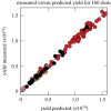
Comparison of data-driven statistical model with actual experimental fusion yields. Over 160 experiments are well described by this predictive model with a wide range of parameters as described in the text. (Online version in colour.)
Figure 8.
Figure 8.
(a) The present illumination geometry for NIF is arranged for cylindrical or near-cylindrical hohlraums. LDD implosion experiments that use this geometry are referred to as PDD; (b) the beam pointing for NIF for PDD; (c) nominal equivalent-target-plane fluence for NIF beams for LDD research. The beams have significant spatial fluence modulations that influence LPI particularly near threshold intensities. (Online version in colour.)
Figure 9.
Figure 9.
(a) Energy scaling of ignition metric χ based in series of highest performing OMEGA experiments to NIF energies; (b) fusion yield scaling with energy with and without alpha amplification. (Online version in colour.)
Figure 10.
Figure 10.
(a) Experimental set-up for CBET experiments on NIF (target and laser pulse); (b) radiographs and simulations of imploding targets with and without wavelength detuning showing effects of CBET reduction at the equator. The mass pileup on the equator shown in the radiographs is a result of more laser absorption at the equator. (Online version in colour.)
Figure 11.
Figure 11.
(a) Scattered-light spectrum from OMEGA and the NIF. The half-harmonic spectrum at OMEGA is characteristic of the two-plasmon-decay instability while the broad spectrum at 600–650 nm is characteristic of convective SRS at electron densities <nc/4 (b) Hot-electron levels inferred from hard X-ray measurements from planar targets where CBET is negligible. The data are taken with 4.5 nsec pulses and with CH targets (one with a thin Si overcoat). The inner and outer beams refer to the different NIF beam cones [25]. (Online version in colour.)
Figure 12.
Figure 12.
(a) Schematic showing that the preheat to the cold shell is a function of both the amount of hot electrons produced, the angular spread of the source, and the transport to the cold shell. (b) Targets with high-Z doping are located at different radial positions in the target and the energy deposited is inferred from the differential X-ray yield. (c) Radial distribution of preheat inferred by differential X-ray yield from radially located Ge-doped CH targets. (Online version in colour.)
Figure 13.
Figure 13.
(a) Three to 4-mm-diam DT-filled capsules for PDD experiments. (b) NIF laser pulse and calculated absorption fraction as a function of time. (c) Measured and 2-D simulations (including CBET and nonlocal electron transport) of fusion yield. (Online version in colour.)
Figure 14.
Figure 14.
(a) Schematic and scattered Thomson-scattered light measured over 120°; (b) schematic showing that scattered light from different angles selects different regions of the EDF; (c) Gaussian order of the EDF dependence on laser intensity compared to simulations. (Online version in colour.)
Figure 15.
Figure 15.
(a) OTS scattered-light spectrum compared to LPSE simulated output. (b) Time history of OTS scattered light compared to LPSE simulation. (c) Two-plasmon-decay-generated hot electrons inferred from X-ray measurements compared to LPSE simulations. (Online version in colour.)
Figure 16.
Figure 16.
(a) TOP9 beam arrangement connecting tunable laser from OMEAG EP to OMEGA 60. (b) Target chamber insertable gas-jet target to create a well-diagnosed plasma. (c) Tunable laser source spectrum (fundamental Nd:glass wavelength is shown); (d) k spectrum options for studying CBET in multiple beam and forward and backward configurations. (Online version in colour.)
Figure 17.
Figure 17.
(a) LPSE calculated target absorption as a function of laser bandwidth; (b) single-beam smoothing time for 1% bandwidth laser (FLUX) and the present SSD system on OMEGA 60. (Online version in colour.)
Figure 18.
Figure 18.
Schematic of advanced laser approach (sum-frequency generation) exploiting optical parametric amplifier technology to generate broadband (greater than 1% bandwidth) UV light (the FLUX laser). (Online version in colour.)

References

    1. Nuckolls J, Wood L, Thiessen A, Zimmerman G. 1972. Laser compression of matter to super-high densities: thermonuclear (CTR) applications. Nature 239, 139–142. ( 10.1038/239139a0) - DOI
    1. Lindl JD. 1998. Inertial confinement fusion: the quest for ignition and energy gain using indirect drive. New York, NY: Springer.
    1. Betti R, Hurricane OA. 2016. Inertial-confinement fusion with lasers. Nat. Phys. 12, 435–448. ( 10.1038/nphys3736) - DOI
    1. Sinars DB, et al. 2020. Review of pulsed power-driven high energy density physics research on Z at Sandia. Phys. Plasmas 27, 070501 ( 10.1063/5.0007476) - DOI
    1. Campbell EM, Hogan WJ. 1999. The National Ignition Facility—Applications for inertial fusion energy and high-energy-density science. Plasma Phys. Control. Fusion 41, B39–B56. ( 10.1088/0741-3335/41/12B/303) - DOI

LinkOut - more resources