Review
. 2020 Nov 16;6(5):1491-1511.
doi: 10.1016/j.bioactmat.2020.11.004. eCollection 2021 May.

Bioinspired mineralized collagen scaffolds for bone tissue engineering

Affiliations
Review

Bioinspired mineralized collagen scaffolds for bone tissue engineering

Zhengwei Li et al. Bioact Mater. .

Abstract

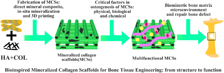
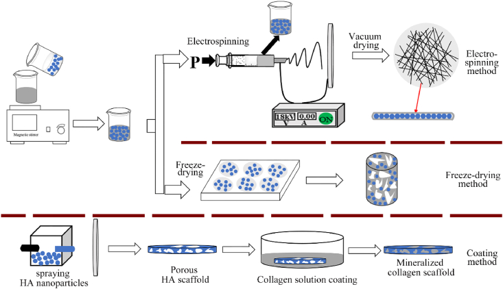
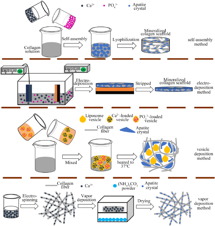
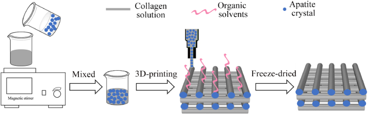
Successful regeneration of large segmental bone defects remains a major challenge in clinical orthopedics, thus it is of important significance to fabricate a suitable alternative material to stimulate bone regeneration. Due to their excellent biocompatibility, sufficient mechanical strength, and similar structure and composition of natural bone, the mineralized collagen scaffolds (MCSs) have been increasingly used as bone substitutes via tissue engineering approaches. Herein, we thoroughly summarize the state of the art of MCSs as tissue-engineered scaffolds for acceleration of bone repair, including their fabrication methods, critical factors for osteogenesis regulation, current opportunities and challenges in the future. First, the current fabrication methods for MCSs, mainly including direct mineral composite, in-situ mineralization and 3D printing techniques, have been proposed to improve their biomimetic physical structures in this review. Meanwhile, three aspects of physical (mechanics and morphology), biological (cells and growth factors) and chemical (composition and cross-linking) cues are described as the critical factors for regulating the osteogenic feature of MCSs. Finally, the opportunities and challenges associated with MCSs as bone tissue-engineered scaffolds are also discussed to point out the future directions for building the next generation of MCSs that should be endowed with satisfactorily mimetic structures and appropriately biological characters for bone regeneration.

Keywords: 3D printing; Biomechanics; Bone repair; Collagen; Mineralization; Scaffold.


Conflict of interest statement

None.

Figures

Image 1
Graphical abstract
Fig. 1
Fig. 1
Mechanical properties of COL, HA, cortical bone and cancellous bone. COL and HA have good toughness and strength respectively, while bone tissue exhibits the characteristics of both materials, showing excellent mechanical properties.
Fig. 2
Fig. 2
The natural bone formation process and the bionic strategy of bone repair scaffold. The new bone formation process follows a bottom-up principle. The hierarchical intrafibrillar mineralized COL are formed by HA and COL and serve as substance for next level, which is an important manifestation of bone hierarchical structure from micro to macro. The hierarchical intrafibrillar mineralized COL undergoes rearrangement and assembly to form fiber bundles. The mineralized fiber bundle is the basic unit of bone matrix and provides the necessary spatial structure for bone formation. The bionics scaffold is fabricated by simulating the process of natural bone formation and provided suitable microenvironment to promote bone repair.
Fig. 3
Fig. 3
The illustration of three direct addition methods for fabricating MCSs. The methods of freeze-drying and coating are relatively simple. Compared with these two methods, the scaffold fabricated by electrospinning is made by fibers accumulation, which structure is more similar to the natural bone matrix.
Fig. 4
Fig. 4
The morphology of MCSs fabricated by electrospinning (A and B), freeze-drying (C) and coating (D) methods and the results of bone cell culture in vitro. A: The schematic diagram of fabrication strategy, morphology and cell compatibility of HA/COL/PLA composite scaffold. The MCSs significantly improved mechanical properties and exhibited excellent cell compatibility. Figure from reference 73. B: SEM images of electrospun Ⅰ) PLA, and Ⅱ) HA/COL/PLA scaffold. The hFob interaction with Ⅲ) PLA and Ⅳ) HA/COL/PLA nanofibrous substrate after culturing 20 days. The HA/COL/PLA scaffold is more advantageous to cell adhesion and proliferation on hFob. Figure from reference 74. C: The COL, S-100 (1:1 HA/COL), and S-500 (5:1 HA/COL) scaffolds fabricated by freeze-drying method. Ⅰ) The SEM images of three scaffolds. Three scaffolds promoted earlier expression of Ⅱ) osteopontin and Ⅲ) osteocalcin at day 14. The MCSs considerably promoted the markers' expression of bone formation. Scale bar = 100 μm. Figure from reference 81. D: The HA, HA-COL scaffolds fabricated by coating method. The control group not executed alkali treatment and collagen coating. Ⅰ) Surface of two scaffolds. Ⅱ) the fluorescent live/dead staining of osteoblasts at 7 days. Ⅲ) morphology and distribution of osteoblasts on two scaffolds at 7 days. The COL-coated group had an observable effect on promoting osteoblasts proliferation, differentiation and mineralization than the control group. Figure from reference 86.
Fig. 5
Fig. 5
The illustration of in-situ mineralization method for fabricating MCSs. Self-assembly, electrodeposition and vesicle deposition methods fabricated MCSs through COL and mineral co-precipitation. Vapor deposition prefabricated the COL scaffold chelated with calcium ions, then provide other mineral ions by vapor deposition.
Fig. 6
Fig. 6
The morphology of MCSs fabricated by self-assembly (A), electrodeposition (B), vesicle deposition (C) and vapor deposition (D) methods and characterization of bone repair effect. A: The SEM image and corresponding unstained TEM images of HIMCSs (Ⅰ), NIMCSs (Ⅱ) and EMCSs (Ⅲ). Rat bone marrow stem cells (rBMSCs) morphology after 1 d of culturing on the Ⅰ, Ⅱ and Ⅲ. The rBMSCs seeded on HIMC showed long filopodia and thick stress fiber formation, which exhibits highly branched “osteocyte‐like” shape. Ⅳ) Bone regeneration in vivo after implantation with Ⅰ, Ⅱ and Ⅲ for 12 weeks. Ⅴ) Bone volume of the defect area from different groups based on micro‐CT test. Ⅵ) Semi‐quantitative analysis of new bone based on histologic examination. Figure from reference 91. B: The morphology of composite scaffold with different COL concentrations: Ⅰ) without COL, Ⅱ)100 mg/L, Ⅲ) 500 mg/L, Ⅳ) cross-sectional morphology of 500 mg/L, Ⅴ) immersed in Ca(OH)2 solution of 500 mg/L. With COL concentration increased, the network structure formed more obvious. After immersing in Ca(OH)2 solutions, the nanofiber structure of MCSs resembled natural bone. Figure from reference 103. C: The SEM image of vesicles only containing COL after dried (Ⅰ). The low magnification SEM image (Ⅱ) and freeze-fracture TEM image (Ⅲ) of mineral/COL composite scaffold (COL concentration = 3.22 mg/ml, [Ca2+] = 26 mM, [P] = 25 mM). The composite scaffold is composed of COL fibers and apatite crystals attached to the surface of vesicle. Figure from reference 106. D: The scaffold's morphology and expression of osteogenic proteins by hFob cells seeded on scaffolds. Ⅰ) pure COL scaffold (ES_Coll), Ⅱ) composite scaffold containing norepinephrine (NE) and Ca2+ (Coll_NE_Ca), Ⅲ) mineralized scaffold fabricated by vapor deposition (Coll_pNE_Ca). The MCSs obtained by vapor deposition method showed extensive roughness and ripples, which indicate that its tensile strength, hardness and toughness increased significantly. The expression of osteocalcin (OCN), osteopontin (OPN), and bone matrix protein 2 (BMP-2) in mineralized scaffold increased meaningfully, which indicates that it has a better performance for new bone formation. Figure from reference 107.
Fig. 7
Fig. 7
The illustration of 3D printing methods for fabricating MCSs. The COL and apatite particles mixed and printed at a low temperature to prepare MCSs containing mineral crystals in fibers.
Fig. 8
Fig. 8
The cell-free and cell-containing 3D printed MCSs and their effects on bone repair in vivo and in vivo. A: The cell-free MCSs fabricated by Low-temperature 3D printing method. Ⅰ) Schematic diagram of preparation strategy and effect of bone repair in vivo. Ⅱ) Measurement of BMSC proliferation on scaffolds using the CCK8 assay at 1, 4, 7, and 11 days after seeding. Ⅲ) ALP activity of BMSCs on scaffolds 7 and 14 days after seeding. Ⅳ)Histological analysis of new bone formation around and within the scaffolds in the rabbit femoral condyle defect model. Group ⅰ-ⅲ represented 3D printed scaffold with various rod widths. Group ⅳ represented nonprinted scaffolds. Group N was the control group, which cultured cells with osteoinductive medium but not seeded on a scaffold. After Van Gieson staining, newly formed bone stains red; the tissue stained dark blue is fibrous tissue. Scale bar: 100 μm. The interconnecting pores within the printed scaffolds facilitated cell penetration and mineralization before the scaffolds degraded and enhanced repair. Figure from reference 127. B: Fabrication schematics and osteogenic activities of cell-loaded scaffolds. Ⅰ) a 3D cell-laden α-TCP/collagen scaffold using cell printing. Ⅱ) Relative alkaline phosphatase (ALP) activity. Ⅲ) Relative calcium deposition and Ⅳ) relative area of OPN images of scaffolds (n = 5). Ⅴ) Optical images of Alizarin Red S (ARS) and osteopontin (OPN) staining of the scaffolds after cell culture for 14 days. CLCS: cell-laden collagen scaffold. TC-CDIP: 3D α-TCP/collagen scaffold was dipped into a cell-laden collagen solution. TC-CPRINT: the cell-laden collagen solution was printed onto 3D α-TCP/collagen scaffold and repeated several times. The cell-loaded scaffold demonstrated significantly higher cellular activities, including metabolic activity and mineralization, compared with the control group. Figure from reference 130.
Fig. 9
Fig. 9
FSS play an important role in promoting COL mineralization. FSS acting on COL fibers promoted the fibers assemble in single direction to form an ordered structure. Figure from reference 146. FSS acting on ACP promoted its transition to HA. FSS acting on composite solution of COL and ACP formed HIM COL.
Fig. 10
Fig. 10
Different types of stem cells promoted new bone formation. A and B: The human skeletal stem cells (hSSCs) isolated from adult human femur tissue (A) and induction of human monocyte-derived iPSCs (B) promoted osteogenic effect. Ⅰ) Experimental strategy (right) and representative FACS plots (left) showing gating scheme for isolation of hSSCs from adult human femurhead tissue. Ⅱ) Alcian blue stain (left) and Alizarin Red stain (right) showing cartilage and bone tissue in a cross-section of micro-mass generated by adult hSSCs after differentiation in vitro. Scale bar, 500 μm and 100 μm, respectively. Ⅲ) IHC staining of cross-section of the ossicle and cartilage for nuclei with DAPI, and bone with anti-collagen II (COL2), and anti-osteocalcin (OSC) antibodies, respectively. Scale bar, 100 μm. C: Isolation of hSSCs from BMP2-treated human adipose stroma (B-HAS). Ⅰ) Experimental strategy for human adipose stroma (HAS) induction with either BMP2 alone or with co-delivery of BMP2 and soluble VEGF receptor (sVEGFR). Ⅱ) Image (left) and MP stain (right) of vascularized ossicle generated 4 weeks after subcutaneous transplantation of HAS treated with BMP2 in NSG mice. Scale bar, 2 mm and 200 μm, respectively. Ⅲ) Bar chart showing quantification of percent contribution by the different skeletal fates to total graft mass for grafts derived from fetal hSSCs, adult hSSCs, skeletal-induced-iPSC, B-HAS, or BMP2 + sVEGFR-treated HAS after morphometric analysis. Figure from reference 154. D: The potential mechanism of RA‐dependent iPSC osteogenesis. Retinoic acid (RA) bound to retinoic acid receptor (RAR), which further activated the downstream pathway to enhance osteogenic gene expression. Figure from reference 155. E: The stem cell microspheroids (CS) and mineralized ECM/stem cell microspheroids (MECS) promoted bone regeneration in rat calvarial bone defects. Ⅰ) Representative micro‐CT images of CS and MECS post‐transplantation in rat calvarial defects at 8 weeks. Ⅱ) Bone volume analysis based on micro‐CT data. Ⅲ) Hematoxylin and eosin (HE) and Masson staining of the engineered bones. Green arrows represent the bone defect margin. Semi‐quantification of new bone (Ⅳ) and osteoblasts/osteocytes (Ⅴ) based on histologic examination. Figure from reference 156.
Fig. 11
Fig. 11
Morphology and bone repair performance of different groups mineralized scaffold. COL/PCL scaffold embedded with HA/TCP (group-I), HA/TCP/rhBMP-2 (group-II), and HA/TCP/PRP (group-III). Live/dead, DAPI/phalloidin, and SEM images of (a) group-I, (b) group-II, and (c) group-III cultured for 7 days. (d) Number of cells and (e) aspect ratio in the live/dead images. (f) Cell proliferation, as determined by the MTT assay. The asterisks indicate significant differences and “NS” denotes non-significance. Groups II and III promoted the development of cytoskeleton and cell relaxation behavior and induced highly active osteogenic activity. Figure from reference 182.
Fig. 12
Fig. 12
The morphology of mineralized collagen fabricated by chemical cross-linking (Ⅰ) and radiation cross-linking (Ⅱ) methods. Ⅰ) morphology and bone repair effect of chemical cross-linked mineralized collagen. TEM image of the HA/Col composite cross-linked with GA (A and B). C–F: Bone tissue reactions of the HA/Col composites with serial cross-linkage concentration. C: Non cross-linked (control), D: 0.0191 mmol/gcol, E: 0.191 mmol/gcol, F: 0.675 mmol/gcol and asterisk (⁎) indicates the HA/Col composite. Neither toxic nor inflammatory reaction was observed. Degradation/resorption with newly bone formation was reduced with increasing GA concentration; however, all composites indicated good bone bonding and osteoconductive properties. Figure from reference 199. Ⅱ) Morphology of different groups MCSs. A: non-mineralized COL without gamma-ray irradiation. B–F: the mineralized crosslinked COL under gamma-ray irradiation of 0, 2, 4, 6 and 8 KGy dose for 24 h. The fiber surface roughness of MCSs increased, and the interconnected COL microfibers (arrows) decreased significantly compared to the non-MCSs. Figure from reference 200.

References

    1. Hassenkam T., Fantner G.E., Cutroni J.A., Weaver J.C., Morse D.E., Hansma P.K. High-resolution AFM imaging of intact and fractured trabecular bone. Bone. 2004;35:4–10. doi: 10.1016/j.bone.2004.02.024. - DOI - PubMed
    1. Taton T.A. Nanotechnology - boning up on biology. Nature. 2001;412:491–492. doi: 10.1038/35087687. - DOI - PubMed
    1. Yerramshetty J.S., Akkus O. The associations between mineral crystallinity and the mechanical properties of human cortical bone. Bone. 2008;42:476–482. doi: 10.1016/j.bone.2007.12.001. - DOI - PubMed
    1. Kruzic J.J., Ritchie R.O. Fatigue of mineralized tissues: cortical bone and dentin. J Mech Behav Biomed Mater. 2008;1:3–17. doi: 10.1016/j.jmbbm.2007.04.002. - DOI - PubMed
    1. Akkus O., Adar F., Schaffler M.B. Age-related changes in physicochemical properties of mineral crystals are related to impaired mechanical function of cortical bone. Bone. 2004;34:443–453. doi: 10.1016/j.bone.2003.11.003. - DOI - PubMed

LinkOut - more resources