. 2020 Dec 7;10(12):403.
doi: 10.3390/membranes10120403.

A New Design of Tubular Ceramic Membrane Module for Oily Water Treatment: Multiphase Flow Behavior and Performance Evaluation

Affiliations

A New Design of Tubular Ceramic Membrane Module for Oily Water Treatment: Multiphase Flow Behavior and Performance Evaluation

Guilherme L Oliveira Neto et al. Membranes (Basel). .

Abstract

Petroleum has been extracted from oil reservoirs using different techniques. This activity is accompanied for a large amount of water and sometimes mixed with gas. This produced water has a high oil concentration and other toxic chemical compounds, thus, it must be treated to be reused or released to environment according to environmental protection regulations. Currently, ceramic membrane technology has been employed in the wastewater treatment, due to its high benefit-cost ratio. In this sense, this work aims to study the oil-water mixture separation process using a new configuration of tubular ceramic membrane module by computational fluid dynamic (ANSYS Fluent software). The proposed model is composed of mass and linear momentum conservation equations coupled to Darcy's law and SST k-ω turbulence model. Results of the volumetric fraction, pressure, and velocity distribution of the oil and water phases are presented and discussed. The results indicated that the proposed model and new device both have great potential to be used on the water/oil separation process and that the transmembrane pressure remains constant in the axial direction and decreases radially through the membranes, indicating an efficient system that favors the transport of clean water and oil retention.

Keywords: ANSYS Fluent; computational fluid dynamics; membrane filtration; produced water.


Conflict of interest statement

The authors declare no conflict of interest.

Figures

Figure 1
Figure 1
Geometric representation of the module under study (a); front view of the separator (b); side view of the separator (c), and top view of the separator (d).
Figure 2
Figure 2
Mesh 2 of the separation module, highlighting the hull, membranes and permeate regions (a), front view (b) and top view (c), used during the computational fluid dynamics (CFD) simulation.
Figure 3
Figure 3
Views of the mesh in vertical longitudinal sections (a,b) and transversal longitudinal sections (c,d).
Figure 4
Figure 4
Transverse planes, in the hull region, chosen for data analysis.
Figure 5
Figure 5
Vertical longitudinal planes (a,b) and horizontal longitudinal planes (c,d) in the hull region, chosen for data analysis.
Figure 6
Figure 6
Vertical longitudinal planes and horizontal longitudinal planes in the membrane region, chosen for data analysis.
Figure 7
Figure 7
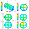
Field of relative oil volumetric fraction in different regions of the hull; (a) general view and in the xy plane at (b) z = 0 mm; (c) z = 30 mm; (d) z = 75 mm; (e) z = 120 mm; and (f) z = 150 mm, of the filtration module during the water/oil separation process.
Figure 8
Figure 8
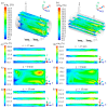
Field of relative oil volumetric fraction in different regions of the hull: (a) In the yz plane at x = −15 mm, x = 0 mm and x = 15 mm; (b) in the xz plane at y = −15 mm, y = 0 mm and y = 15 mm; (c) x = −15 mm; (d) y = −15 mm; (e) x = 0 mm; (f) y = 0 mm; (g) x = 15 mm and (h) y = 15 mm, of the filtration module during the water / oil separation process.
Figure 9
Figure 9
Field of relative oil volumetric fraction in different regions of membrane 1 (a), membrane 2 (b), membrane 3 (c), and membrane 4 (d) that make up the filtration module during the water/oil separation process.
Figure 10
Figure 10
Iso-surfaces of the relative oil volumetric fraction in different regions of the permeated in the filtration module during the water/oil separation process: (a) α/α0=0.25%; (b) α/α0=0.5%; (c) α/α0=1%; (d) α/α0=5%; (e) α/α0=50% and (f) α/α0=75%.
Figure 11
Figure 11
Pressure field in different regions of the hull. (a) Overview and in the xy plane at z = 0 mm (b), z = 30 mm (c), z = 75 mm (d), z = 120 mm (e), and z = 150 mm (f), of the filtration module during the water / oil separation process.
Figure 12
Figure 12
Pressure on the membrane at different (a) horizontal and (b) vertical points (z = 30, 75, and 120 mm) of the filtration module during the water/oil separation process.
Figure 13
Figure 13
Velocity distribution of the fluid mixture inside the membranes and permeated in the filtration module during the water/oil separation process: (a) membrane 1; (b) membrane 2; (c) membrane 3 and (d) membrane 4.
Figure 14
Figure 14
Vector velocity field of permeate in the four membranes of the filtration module during the water/oil separation process: (a) permeate 1; (b) permeate 2; (c) permeate 3 and (d) permeate 4.
Figure 15
Figure 15
Axial permeate velocity at different (a) horizontal and (b) vertical points along the membrane collecting tube, at z = 30, 75, and 120 mm, of the filtration module during the water/oil separation process.

References

    1. Jiménez S., Micó M.M., Arnaldos M., Medina F., Contreras S. State of the art of produced water treatment. Chemosphere. 2018;192:186–208. doi: 10.1016/j.chemosphere.2017.10.139. - DOI - PubMed
    1. Huang K.Z., Xie Y.F., Tang H.L. Formation of disinfection by-products under influence of shale gas produced water. Sci. Total Environ. 2019;647:744–751. doi: 10.1016/j.scitotenv.2018.08.055. - DOI - PubMed
    1. Fakhru’l-Razi A., Pendashteh A., Abdullah L.C., Biak D.R.A., Madaeni S.S., Abidin Z.Z. Review of technologies for oil and gas produced water treatment. J. Hazard. Mater. 2009;170:530–551. doi: 10.1016/j.jhazmat.2009.05.044. - DOI - PubMed
    1. Igunnu E.T., Chen G.Z. Produced water treatment technologies. Int. J. Low-Carbon Technol. 2014;9:157–177. doi: 10.1093/ijlct/cts049. - DOI
    1. Khan F.A., Hisham S., Ghasemi M. Oil field produced water recovery and boosting the quality for using in membrane less fuel cell. SN Appl. Sci. 2019;1:510. doi: 10.1007/s42452-019-0523-3. - DOI

LinkOut - more resources