. 2020 Dec;36(6):1649-1668.
doi: 10.1109/TRO.2020.3005533. Epub 2020 Jul 13.

Design and Validation of a Powered Knee-Ankle Prosthesis with High-Torque, Low-Impedance Actuators

Affiliations

Design and Validation of a Powered Knee-Ankle Prosthesis with High-Torque, Low-Impedance Actuators

Toby Elery et al. IEEE Trans Robot. 2020 Dec.

Abstract

We present the design of a powered knee-ankle prosthetic leg, which implements high-torque actuators with low-reduction transmissions. The transmission coupled with a high-torque and low-speed motor creates an actuator with low mechanical impedance and high backdrivability. This style of actuation presents several possible benefits over modern actuation styles in emerging robotic prosthetic legs, which include free-swinging knee motion, compliance with the ground, negligible unmodeled actuator dynamics, less acoustic noise, and power regeneration. Benchtop tests establish that both joints can be backdriven by small torques (~1-3 Nm) and confirm the small reflected inertia. Impedance control tests prove that the intrinsic impedance and unmodeled dynamics of the actuator are sufficiently small to control joint impedance without torque feedback or lengthy tuning trials. Walking experiments validate performance under the designed loading conditions with minimal tuning. Lastly, the regenerative abilities, low friction, and small reflected inertia of the presented actuators reduced power consumption and acoustic noise compared to state-of-art powered legs.

Keywords: actuator design; backdrivability; powered prostheses; rehabilitation robotics.


Figures

Fig. 1.
Fig. 1.
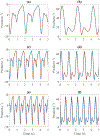
Ankle (a & c) and knee (b & d) average joint powers and torques for healthy individuals (75 kg) [39], used for defining peak requirements of the powered prosthesis. Solid blue lines indicate level ground walking at fast speeds, where dotted red lines and dashed black lines represent stair ascent and descent, respectively.
Fig. 2.
Fig. 2.
Final assemblies of the prosthetic leg. The image on the left displays the first version of the prosthesis (without batteries), which was used in benchtop and able-bodied testing. The image on the right displays the prosthesis after revisions were made for amputee experiments (i.e., torque sensor removal and on-board batteries).
Fig. 3.
Fig. 3.
CAD model of the planetary gear transmission. The image on the left illustrates an exploded view of the entire transmission (including planet carriers), while the right demonstrates the gear layout after assembly.
Fig. 4.
Fig. 4.
Block Diagram of Electrical System: The system’s computer receives feedback related to the user’s gait and sends torque commands to the motor drivers. Torque sensors are indicated in dashed boxes to represent their presence during benchtop and able-bodied testing but absence for amputee testing.
Fig. 5.
Fig. 5.
CAD design of the knee actuator. The exploded view on the left displays the components/sub-assemblies of the knee actuator, such as the upper/lower hinges, encoders, transmission, motor, and pylon. The image on the right presents the assembled knee actuator. The pyramid adapter on top connects to the user’s socket, and the length-adjustable pylon on bottom connects to the ankle actuator module.
Fig. 6.
Fig. 6.
CAD design of the ankle actuator. The image on the left presents the assembled ankle actuator. The exploded view on the right displays the components/sub-assemblies of the ankle actuator, such as the motor, structure, 4-bar linkage, transmission, electronics, and foot.
Fig. 7.
Fig. 7.
(a) Finite state machine (FMS) for walking control. Blue rectangles and green ellipses indicate time-based (position control) and impedance-based states, respectively. (b) Definition of the joint angles.
Fig. 8.
Fig. 8.
Benchtop torque tests. (a) Experimental setup for backdrive torque test. (b) Measured torque during peak torque tests.
Fig. 9.
Fig. 9.
Experimental setup for free swing test. The photo on the left shows the unpowered leg when the knee was held in flexion. The photo on the right shows the shank of the leg in motion after being released.
Fig. 10.
Fig. 10.
Recorded position of the knee as it returns to zero following release from an initial offset.
Fig. 11.
Fig. 11.
Bode plots for closed-loop position bandwidth tests. Inputs with amplitudes of 5, 10, and 15 degrees produce cutoff frequencies of approximately 134.0, 90.1, and 67.4 rad/s, or 21.3, 14.3, and 10.7 Hz, respectively.
Fig. 12.
Fig. 12.
Position tracking of normative gait trajectories at various frequencies. Solid blue and dotted red lines denote the desired and measured position, respectively. Plots a), c), and e) present ankle tracking at 0.5, 1.0, and 1.3 Hz, respectively. Plots b), d), and f) present knee tracking at 0.5, 1.0, and 1.3 Hz, respectively.
Fig. 13.
Fig. 13.
Open-loop impedance of the ankle joint with various Kp and Kd gains. Solid blue and dotted red lines correspond to commanded and measured torque, respectively. PD gains used are: a) Kp=0 and Kd=29, b) Kp=46 and Kd=3, c) Kp=46 and Kd=3, and d) Kp=172 and Kd=9.
Fig. 14.
Fig. 14.
Experimental setup for able-bodied walking experiments. The image on the left shows the subject, safety harness, treadmill, and sound level meter. The image on the right shows how the prosthetic leg was connected to the bypass adapter, and how it was attached to the subject’s leg.
Fig. 15.
Fig. 15.
Experimental setup for amputee walking experiments. Both images show the amputee subject wearing the prosthesis on the instrumented treadmill. Note that although the batteries were mounted to the leg during these experiments, the leg was powered by identical off-board batteries to allow for the off-board measurement of current and voltage.
Fig. 16.
Fig. 16.
Prosthetic (PR) knee and ankle joint position during able-bodied walking with the prosthesis. Solid blue and dotted red lines correspond to the average ankle and knee joint angles, respectively for speeds: a) 0.9 m/s b) 1.1 m/s c) 1.3 m/s d) 1.6 m/s. Standard deviations (±1) are indicated by shaded regions around the mean. Normative (Norm) knee and ankle trajectories [39] (not available for 1.6 m/s) are shown as a reference in green dash-dotted and gray dashed lines, respectively.
Fig. 17.
Fig. 17.
Average knee commanded and measured torque during able-bodied gait. Solid blue and dotted red lines correspond to the commanded and measured torque, respectively, for speeds: a) 0.9 m/s b) 1.1 m/s c) 1.3 m/s d) 1.6 m/s. Standard deviations (±1) are indicated by shaded regions around the mean.
Fig. 18.
Fig. 18.
Average ankle commanded and measured torque during able-bodied gait. Solid blue and dotted red lines correspond to the commanded and measured torque, respectively, for speeds: a) 0.9 m/s b) 1.1 m/s c) 1.3 m/s d) 1.6 m/s. Standard deviations (±1) are indicated by shaded regions around the mean.
Fig. 19.
Fig. 19.
Average power per gait cycle of the prosthetic leg at different walking speeds for the able-bodied subject at a) 0.9 m/s, b) 1.1 m/s, c) 1.3 m/s, and d) 1.6 m/s. Solid blue lines indicate power calculated from measured current and voltage to and from the batteries. Dotted red lines indicate power calculated from measured torque and velocity. Dashed gray and dash-dotted green lines indicate mechanical joint power from measured torque and velocity for the ankle and knee, respectively.
Fig. 20.
Fig. 20.
Acoustic sound level during gait at a) 0.9 m/s, b) 1.3 m/s. Solid blue, dotted red, dashed gray, and dash-dotted green lines represents the presented prosthetic leg with low-impedance actuators, a traditional powered prosthetic leg with high-impedance actuators, an able-bodied subject, and ambient sound levels, respectively, during treadmill walking. Ground contact of the prosthetic leg starts at 0% of the gait cycle.
Fig. 21.
Fig. 21.
Prosthetic (PR) knee and ankle joint position during amputee walking with the prosthesis. Solid blue and dotted red lines correspond to the average ankle and knee joint angles, respectively for speeds: a) 0.9 m/s b) 1.1 m/s c) 1.3 m/s d) 1.6 m/s. Standard deviations (±1) are indicated by shaded regions around the mean. Normative (Norm) knee and ankle trajectories [39] (not available for 1.6 m/s) are shown as a reference in green dash-dotted and gray dashed lines, respectively.
Fig. 22.
Fig. 22.
Average power per gait cycle of the prosthetic leg at different walking speeds for the amputee subject at a) 0.9 m/s, b) 1.1 m/s, c) 1.3 m/s, and d) 1.6 m/s. Solid blue lines indicate power calculated from measured current and voltage to and from the batteries. Dotted red lines indicate power calculated from measured torque and velocity. Dashed gray and dash-dotted green lines indicate mechanical joint power from measured torque and velocity for the ankle and knee, respectively.
Fig. 23.
Fig. 23.
Magnitude plot for open-loop frequency response tests. This displays the DC offset and and cutoff frequency used to determine actuator impedance and damping.
Fig. 24.
Fig. 24.
Stability margins for three different human stiffness values, Kh = 100, 1000, and 10,000 Nm/rad. The region above the margins is the stable region.

References

    1. Miller W, Deathe A, Speechley M, and Koval J, “The influence of falling, fear of falling, and balance confidence on prosthetic mobility and social activity among individuals with a lower extremity amputation,” Arch. Phys. Med. Rehab, vol. 82, no. 9, pp. 1238–1244, 2001. - PubMed
    1. Gailey RS, Wenger MA, Raya M, Kirk N, Erbs K, Spyropoulos P, and Nash MS, “Energy expenditure of trans-tibial amputees during ambulation at self-selected pace,” Prosthetics Orthotics Int, vol. 18, no. 2, p. 84, 1994. - PubMed
    1. Kaufman KR, Frittoli S, and Frigo CA, “Gait asymmetry of transfemoral amputees using mechanical and microprocessor-controlled prosthetic knees,” Clin. Biomechanics, vol. 27, no. 5, pp. 460–465, 2012. - PMC - PubMed
    1. Lambrecht BG and Kazerooni H, “Design of a semi-active knee prosthesis,” in IEEE Int. Conf. Robot. Automat, 2009, pp. 639–645.
    1. Berry D, “Microprocessor prosthetic knees,” Physical Medicine and Rehabilitation Clinics, vol. 17, no. 1, pp. 91–113, 2006. - PubMed

LinkOut - more resources