Review
. 2020 Nov 24;23(12):101846.
doi: 10.1016/j.isci.2020.101846. eCollection 2020 Dec 18.

Emerging Materials for Neuromorphic Devices and Systems

Affiliations
Review

Emerging Materials for Neuromorphic Devices and Systems

Min-Kyu Kim et al. iScience. .

Abstract

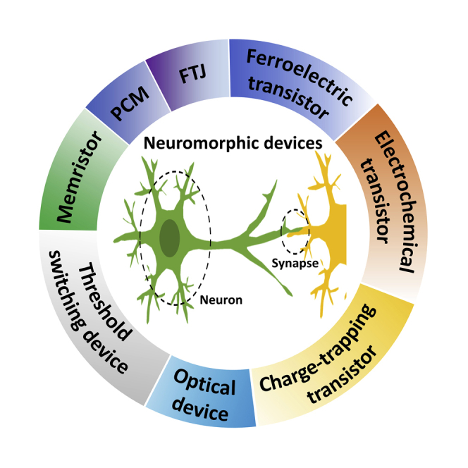
Neuromorphic devices and systems have attracted attention as next-generation computing due to their high efficiency in processing complex data. So far, they have been demonstrated using both machine-learning software and complementary metal-oxide-semiconductor-based hardware. However, these approaches have drawbacks in power consumption and learning speed. An energy-efficient neuromorphic computing system requires hardware that can mimic the functions of a brain. Therefore, various materials have been introduced for the development of neuromorphic devices. Here, recent advances in neuromorphic devices are reviewed. First, the functions of biological synapses and neurons are discussed. Also, deep neural networks and spiking neural networks are described. Then, the operation mechanism and the neuromorphic functions of emerging devices are reviewed. Finally, the challenges and prospects for developing neuromorphic devices that use emerging materials are discussed.

Keywords: Devices; Electronic Materials; Materials Design; Memory Structure.


Figures

None
Graphical abstract
Figure 1
Figure 1
Biological Neurons and Functions (A) Schematic illustration of neuron in a biological system. Reproduced with permission (Lee et al., 2020). Copyright 2020, MDPI AG. (B) Integrate-and-fire characteristics (bottom) in L5 pyramidal neuron as a response to fluctuating input current (top). Reproduced with permission (Pozzorini et al., 2015). Copyright 2015, Public Library of Science.
Figure 2
Figure 2
Biological Synapse and Learning Rules (A) Schematic illustration of the synapse in a biological system. Reproduced with permission (John et al., 2018). Copyright 2018, John Wiley & Sons, Inc. (B) Long-term potentiation characteristics (top) found in hippocampus of the anesthetized rabbit. Long-term depression (bottom) characteristics in climbing fiber synapse. Reproduced with permission (Bliss and Lømo, 1973). Copyright 1973, John Wiley & Sons, Inc. Reproduced with permission (Hansel and Linden, 2000). Copyright 2000, Elsevier Science Ltd. (C) Types of STDP including symmetric Hebbian and anti-Hebbian; asymmetric Hebbian and anti-Hebbian learning rules. Reproduced with permission (Sharbati et al., 2018). Copyright 2018, John Wiley & Sons, Inc. (D) STDP of biological synapse. Reproduced with permission (Bi and Poo, 1998). Copyright 1998, Society for Neuroscience.
Figure 3
Figure 3
Neural Networks (A) Schematic illustrations of neural networks composed of input, hidden, and output neurons. Each neuron is connected by synapses to all the neurons in the next neuron layer. (B and C) Schematic illustration of (B) DNNs and (C) SNNs. In DNNs, the inputs (x) from pre-synaptic neuron are multiplied by synaptic weights (w) and then are fed to the post-synaptic neurons. In SNNs, a neuron receives spikes from several inputs and then fires output spikes.
Figure 4
Figure 4
Two-Terminal Artificial Synapses for DNNs (A) Schematic illustration of CιC:Ag-based memristor during switching. (B) Resistive switching behaviors and set voltage variation of CιC:Ag-based memristor. (C) Potentiation/depression characteristics of CιC:Ag-based memristor. Reproduced with permission (Ge et al., 2020). Copyright 2020, The Royal Society of Chemistry. (D) Schematic operation mechanism of PCM. The crystalline region can be gradually increased by application of potentiation pulses. (E) The potentiation characteristics of PCM based on GST with different programming current amplitudes (Iprog). Reproduced with permission (Boybat et al., 2018). Copyright 2018, Springer Nature. (F) Gradual reset and set characteristic of PCM based on GST. Gradual reset is performed by using pulses with incremental amplitude from 2 to 4 V (20-mV voltage steps). Gradual set is performed by using staircase pulse scheme including 20 pulses for each voltage step (0.5, 0.6, 0.7, 0.8, and 0.9 V). Reproduced with permission (Kuzum et al., 2012a). Copyright 2012, American Chemical Society. (G) Schematic illustration of an FTJ-based artificial synapse with Pt/BaTiO3 (BTO)/Nb-doped SrTiO3 (SNTO) structure. (H) Multiple conductance-voltage (G-V) hysteresis loop as a function of pulse width. (I) Potentiation and depression characteristics with 200 states for 500 cycles. Positive voltage (1.3 V, 50 ns) and negative voltage pulses (−1.75, 50 ns) pulses were used for potentiation and depression operation, respectively. Reproduced with permission (Li et al., 2020a). Copyright 2020, John Wiley & Sons, Inc.
Figure 5
Figure 5
Three-Terminal Artificial Synapses for DNNs (A) Schematic illustration of electrochemical transistor with a Li3POxSex electrolyte. (B and C) Conductance modulation characteristics of electrochemical transistor based on (B) Li3PO4 and (C) Li3POxSex. (D) Potentiation/depression of Li3POxSex-based electrochemical transistor using 90 identical pulses (±1.5 V, 1 s). Reproduced with permission (Nikam et al., 2019). Copyright 2019, Springer Nature. (E) Schematic illustration of ferroelectric transistor composed of HfZrOx and poly-GeSn. (F and G) (F) Potentiation and (G) depression characteristics of devices using HfZrOx. Reproduced with permission (Chou et al., 2020). Copyright 2020, American Chemical Society. (H) Schematic illustration of charge-trapping transistor with IGZO:Al NPs/Al2O3/p+ Si structure. (I) Schematic operation mechanism of charge-trapping transistor. (J) Potentiation/depression of charge-trapping transistor. Reproduced with permission (Kim et al., 2020a). Copyright 2020, John Wiley & Sons, Inc.
Figure 6
Figure 6
Two-Terminal Artificial Synapses for SNN (A) Schematic illustration of neural network composed of CMOS neurons and memristor synapses. (B) STDP characteristics obtained using a memristor synapse (left) and a hippocampal neuron of a rat (right). Insets: scanning-electron microscope image of a memristor crossbar array. Scale bar: 300 nm (left). A phase contrast image of a hippocampal neuron. Scale bar: 50 μm (right). Reproduced with permission (Jo et al., 2010). Copyright 2010, American Chemical Society. (C) Schematic illustration of 1T1R synapse. The pre-synaptic neuron (PRE) and the post-synaptic neuron (POST) are connected to gate electrode and the source of the transistor, respectively. The POST is also connected to the resistor to apply feedback spike to the 1T1R synapse. (D) Synaptic weight change after PRE (Vaxon) and POST (VTE) spikes. Short (left) and long (right) delays (Δt = tPRE-tPOST) lead to strong and weak potentiation, respectively. (E) Relative synaptic weight change (G/G0) depending on Δt. Reproduced with permission (Wang et al., 2018a). Copyright 2018, American Association for Advancement of Science. (F) Resistance hysteresis loops of synaptic FTJs depending on voltage pulse amplitudes. (G and H) STDP learning rules with (G) asymmetric and (H) symmetric forms obtained using FTJs. Reproduced with permission (Majumdar et al., 2019). Copyright 2019, John Wiley & Sons, Inc.
Figure 7
Figure 7
Three-Terminal Devices for SNN (A) Schematic structure of the device composed of P3HT and ion-gel. (B) Asymmetric STDP characteristics of P3HT-based artificial synapse. (C) Waveforms of pre- and post-spikes to achieve STDP. Reproduced with permission (Fu et al., 2018). Copyright 2018, American Chemical Society. (D) Schematic illustration of carbon nanotube (CNT) synaptic transistor and atomic force microscopic images of single-walled CNT. (E) STDP function in the device CNT-based artificial synapse. (F) The architecture of artificial neural networks using CNT synaptic transistor. Reproduced with permission (Kim et al., 2015). Copyright 2015, American Chemical Society. (G) Schematic structure of the device composed of P(VDF-TrFE) and pentacene. (H) Transfer characteristics of the ferroelectric organic neuromorphic transistor. (I) Implementation of the asymmetric STDP functions using organic-based artificial synapse. Reproduced with permission (Jang et al., 2019b). Copyright 2019, American Chemical Society.
Figure 8
Figure 8
Artificial Neurons Based on Memristors (A) Schematic illustration of biological neurons and synapse. Signals are transferred from pre-to post-synaptic neuron through a synapse. (B) Equivalent electronic systems to a biological synapse. Neurons accumulate inputs generated by different pre-synaptic neurons and fire spikes to the next synapse. Reproduced with permission (Hua et al., 2019). Copyright 2019, John Wiley & Sons, Inc. (C) Operation principle of threshold switching-based artificial neuron. (D) Integrate-and-fire behavior of an artificial neuron based on B0.25Te0.75 (B-Te) at different current amplitudes. Reproduced with permission (Lee et al., 2019). Copyright 2019, John Wiley & Sons, Inc. (E) Oscillation of voltage across the diffusive memristor under application of voltage pulse (1 V). (F) A magnified view of the oscillation. (G) The oscillation frequency of neuron depending on the resistance of a load memristor. Reproduced with permission (Midya et al., 2019). Copyright 2019, John Wiley & Sons, Inc.
Figure 9
Figure 9
Artificial Neurons Based on Ferroelectric Transistor (A) Schematic illustration of ferroelectric transistor based on TiN/Si:HfO2/SiON/Si. (B) Implementation of integrate-and-fire functions using a ferroelectric transistor. (C) Consecutive integrate-and-fire behaviors with different voltage amplitudes. Reproduced with permission (Mulaosmanovic et al., 2018a). Copyright 2018, The Royal Society of Chemistry.
Figure 10
Figure 10
Artificial Neurons Based on Phase Change Materials and Photonic Application (A) Relative change in conductance (G/G0) depending on the number of pulses (Nc). (B) Average Nc to reach a threshold conductance (Gth = Gsat/2) depending on pulse amplitude for set process (Vset) and reset process (Vreset). (C) Integrate-and-fire characteristics in a phase change neuron. The firing frequency of the artificial neuron can be controlled by the amplitude of the applied voltage pulse. Reproduced with permission (Pedretti et al., 2020). Copyright 2020, Pedretti et al. (D) Schematic illustration of the ring resonator with GST. The transmission of light through DROP and THROUGH port can be controlled by crystalline state of GST. (E) Schematic illustration of photonic neuron based on GST-embedded ring resonator. (F) Change of membrane potential in photonic neuron after write and reset pulses. Reproduced with permission (Chakraborty et al., 2018). Copyright 2018, Springer Nature. (G) I-V characteristics under dark and UV illumination in memristor based on InP/ZnS core-shell QDs. (H) Schematic illustrations of biological neuron and neuromorphic circuit using the InP/ZnS-based memristor. (I) Integration-and-fire behavior emulated by InP/ZnS-based memristor. Reproduced with permission (Wang et al., 2020). Copyright 2020, John Wiley & Sons, Inc.

References

    1. Abbott L.F., Nelson S.B. Synaptic plasticity: taming the beast. Nat. Neurosci. 2000;3:1178–1183. - PubMed
    1. Abeles M., Bergman H., Margalit E., Vaadia E. Spatiotemporal firing patterns in the frontal cortex of behaving monkeys. J. Neurophysiol. 1993;70:1629–1638. - PubMed
    1. Abraham W.C. Metaplasticity: tuning synapses and networks for plasticity. Nat. Rev. Neurosci. 2008;9:387. - PubMed
    1. Alessandri C., Pandey P., Abusleme A., Seabaugh A. Switching dynamics of ferroelectric Zr-Doped HfO2. IEEE Electron Device Lett. 2018;39:1780–1783.
    1. Ali T., Polakowski P., Büttner T., Kämpfe T., Rudolph M., Pätzold B., Hoffmann R., Czernohorsky M., Kühnel K., Steinke P. Theory and experiment of Antiferroelectric (AFE) Si-Doped Hafnium Oxide (HSO) enhanced floating-gate memory. IEEE Trans. Electron Devices. 2019;66:3356–3364.

LinkOut - more resources