. 2020 Dec 15;10(1):21981.
doi: 10.1038/s41598-020-78613-7.

Zeroth- and first-order long range non-diffracting Gauss-Bessel beams generated by annihilating multiple-charged optical vortices

Affiliations

Zeroth- and first-order long range non-diffracting Gauss-Bessel beams generated by annihilating multiple-charged optical vortices

Lyubomir Stoyanov et al. Sci Rep. .

Abstract

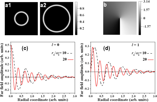
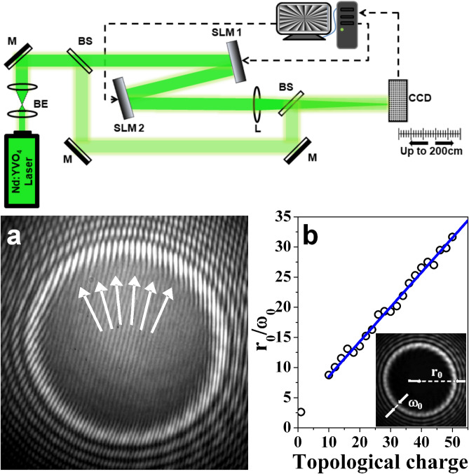
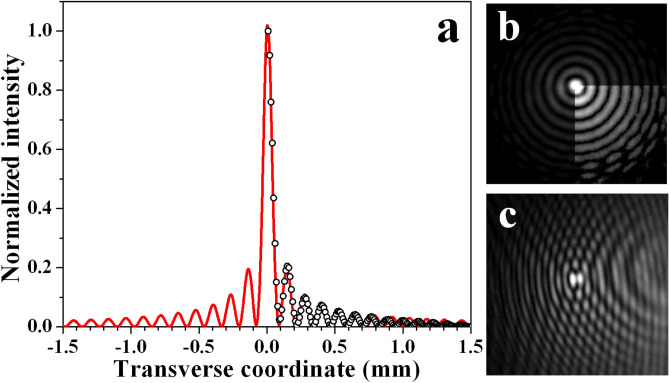
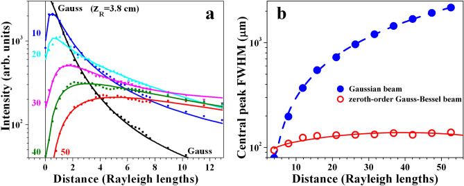
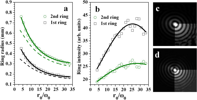
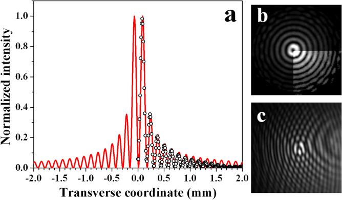
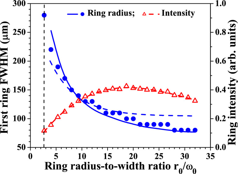
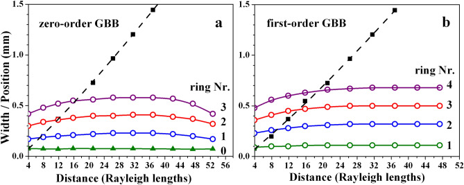
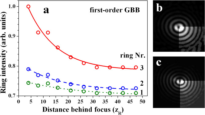
We demonstrate an alternative approach for generating zeroth- and first-order long range non-diffracting Gauss-Bessel beams (GBBs). Starting from a Gaussian beam, the key point is the creation of a bright ring-shaped beam with a large radius-to-width ratio, which is subsequently Fourier-transformed by a thin lens. The phase profile required for creating zeroth-order GBBs is flat and helical for first-order GBBs with unit topological charge (TC). Both the ring-shaped beam and the required phase profile can be realized by creating highly charged optical vortices by a spatial light modulator and annihilating them by using a second modulator of the same type. The generated long-range GBBs are proven to have negligible transverse evolution up to 2 m and can be regarded as non-diffracting. The influences of the charge state of the TCs, the propagation distance behind the focusing lens, and the GBB profiles on the relative intensities of the peak/rings are discussed. The method is much more efficient as compared to this using annular slits in the back focal plane of lenses. Moreover, at large propagation distances the quality of the generated GBBs significantly surpasses this of GBBs created by low angle axicons. The developed analytical model reproduces the experimental data. The presented method is flexible, easily realizable by using a spatial light modulator, does not require any special optical elements and, thus, is accessible in many laboratories.


Conflict of interest statement

The authors declare no competing interests.

Figures

Figure 1
Figure 1
Distribution of the input electric field amplitude E of the light beam described by Eq. (6) for r0/ω0=10 (panel (a1)) and 20 (panel (a2)), where ω0=const. Panel (b)—typical phase profile of the central peak of the first-order GBB. Radial distributions according to Eq. (10) of the far field electric field amplitudes E of zeroth- (c) and first-order GBBs (d) for r0/ω0=10 (black dashed curves) and 20 (red solid curves).
Figure 2
Figure 2
Top—experimental setup. Nd:YVO4, continuous-wave frequency-doubled solid-state laser emitting at a wavelength λ=532 nm; BS, beam splitters; M, flat silver mirrors; SLM, reflective spatial light modulators (model Pluto, Holoeye Photonics); L, focusing lens (diameter 2.5 cm, f=100 cm); CCD, charge-coupled device camera. Bottom: (a) Magnified interference pattern recorded in front of the lens when SLM1 is programmed to imprint on the flat phase front of the incoming Gaussian beam the helical phase of an optical vortex with a topological charge 25. SLM2 is switched off. Arrows point to the positions of 6 from the 25 decayed OVs. (b) Dependence of the ring radius-to-width ratio r0/ω0 on the topological charge encoded by one of the SLMs at a fixed distance of 50 cm behind it. Inset (shrunken): Intensity distribution of the bright vortex ring shown in panel (a) when the reference arm of the interferometer is blocked, with designation of r0 and ω0.
Figure 3
Figure 3
(a) Radial intensity profile of the zeroth-order GBB (hollow circles) generated by annihilating OV with a |TC|=21 (r0/ω0=15.0 in the plane of the lens) and the respective numerically generated transverse beam cross-section (red solid curve). Power density distribution of this GBB (b) and interference pattern (c) obtained by overlapping it with an offset spherical wave. The CCD camera is located 15 cm (4 Rayleigh diffraction lengths zR of the focused pure Gaussian beam) behind the focus of the lens.
Figure 4
Figure 4
Blue dots/solid line and left scale: Experimental dependence of the full width at half maximum (FWHM) of the central peak of the zeroth-order GBB on the radius-to-width ratio r0/ω0 of the bright ring measured in the plane of the lens. Blue dashed curve - numerical result obtained using Eq. (10). Red triangles/solid line and right scale: Central peak intensity vs. r0/ω0 extracted from the same set of experimental data. The CCD camera is located 45 cm (12 Rayleigh diffraction lengths zR of the focused pure Gaussian beam) behind the focus of the lens.
Figure 5
Figure 5
Graph (a)—intensity of the Gaussian beam vs. propagation distance behind the focus of the lens (black curve) in units of Rayleigh diffraction length (zR=3.8 cm). For comparison, the variation of the central peak intensity of the Gauss-Bessel beams vs. distance (in units of zR) are shown for |TC|=10, 20, 30, 40, and 50 corresponding to r0/ω0= 8.7, 14.8, 21.2, 29.2, and 31.6 (color lines). Graph (b)—measured width (FWHM) of a Gaussian beam (blue solid dots) and of the central peak of the Gauss–Bessel beam (red hollow circles) vs. free space propagation distance (in units of zR, in the particular measurement—from 15 to 200 cm behind the focus of the lens). The GBB is generated using OVs with topological charges |TC|=30 on the SLMs ensuring r0/ω0=21.2 in the plane of the lens.
Figure 6
Figure 6
Decrease of the radii of the 1st and 2nd ring of the zeroth-order GBB (a) vs. r0/ω0. Dashed curves - numerical results obtained using Eq. (10). Respective increase of the peak intensities (b) with increasing the bright ring radius-to-width ratio r0/ω0 in the plane of the focusing lens. Frames (c,d)—GBBs generated in the cases r0/ω0=14.8 and 29.2 (using OVs with |TC|=20 and 40) indicating that the number of unperturbed rings increases with r0/ω0. The data are recorded 45 cm (12zR) behind the focus of the lens.
Figure 7
Figure 7
(a) Radial intensity profile of the first-order Gauss-Bessel beam (hollow circles) generated by annihilating 20 from the total 21 OVs (r0/ω0=15 in the plane of the lens) and numerical fit (red solid curve). Power density distribution of this GBB (b) for the same r0/ω0 and interference pattern (c) obtained by overlapping it with an offset spherical wave. The data are recorded 15 cm (4zR) behind the focus of the lens.
Figure 8
Figure 8
Blue dots/solid line and left scale: Dependence of the first ring radius (FWHM) of the first-order GBB on the r0/ω0. (One OV remains nested in the beam causing its central part to be doughnut-shaped.) Blue dashed curve—numerical result obtained using Eq. (10). Red triangles/dashed line and right scale: Azimuthally-averaged first ring intensity vs. r0/ω0 extracted from the same set of data. The data are recorded 45 cm (12zR) behind the focus of the lens.
Figure 9
Figure 9
Direct comparison between the width of the central peak for zeroth-order GBB and the positions of the first coaxial bright rings (graph (a)) and respective data for first-order GBB (graph (b)) vs. free space propagation distance in units of Rayleigh lengths (zR=3.8 cm). Black solid squares and dashed line-width of the pure Gaussian beam when the two SLMs are switched off.
Figure 10
Figure 10
(a) Azimuthally-averaged peak intensity of the first three rings of the first-order GBB for r0/ω0=21.4 (annihilating OVs with TC=30,-31). (b,c) first-order GBBs generated using TC=20,-21 and TC=40,-41 (r0/ω0= 15.0 and 30.0, respectively), indicating that the number of unperturbed rings increases with r0/ω0 and with |TC|.

References

    1. Durnin, J. Exact solutions for nondiffracting beams. I. The scalar theory. J. Opt. Soc. Am. A4, 651–654 (1987).
    1. Khonina SN, Ustinov AV, Chávez-Cerda S. Generalized parabolic nondiffracting beams of two orders. J. Opt. Soc. Am. A. 2018;35:1511–1517. doi: 10.1364/JOSAA.35.001511. - DOI - PubMed
    1. Bouchal Z. Nondiffracting optical beams: Physical properties, experiments, and applications. Czech. J. Phys. 2003;53:537–578. doi: 10.1023/A:1024802801048. - DOI
    1. McGloin D, Dholakia K. Bessel beams: Diffraction in a new light. Contemp. Phys. 2005;46:15–28. doi: 10.1080/0010751042000275259. - DOI
    1. Miceli J, Durnin Jr JJ, Eberly JH. Diffraction-free beams. Phys. Rev. Lett. 1987;58:1499–1501. doi: 10.1103/PhysRevLett.58.1499. - DOI - PubMed