. 2020 Dec 18;3(1):786.
doi: 10.1038/s42003-020-01518-8.

Submolecular probing of the complement C5a receptor-ligand binding reveals a cooperative two-site binding mechanism

Affiliations

Submolecular probing of the complement C5a receptor-ligand binding reveals a cooperative two-site binding mechanism

Andra C Dumitru et al. Commun Biol. .

Erratum in

Abstract

A current challenge to produce effective therapeutics is to accurately determine the location of the ligand-biding site and to characterize its properties. So far, the mechanisms underlying the functional activation of cell surface receptors by ligands with a complex binding mechanism remain poorly understood due to a lack of suitable nanoscopic methods to study them in their native environment. Here, we elucidated the ligand-binding mechanism of the human G protein-coupled C5a receptor (C5aR). We discovered for the first time a cooperativity between the two orthosteric binding sites. We found that the N-terminus C5aR serves as a kinetic trap, while the transmembrane domain acts as the functional site and both contributes to the overall high-affinity interaction. In particular, Asp282 plays a key role in ligand binding thermodynamics, as revealed by atomic force microscopy and steered molecular dynamics simulation. Our findings provide a new structural basis for the functional and mechanistic understanding of the GPCR family that binds large macromolecular ligands.


Conflict of interest statement

The authors declare no competing interests.

Figures

Fig. 1
Fig. 1. FD-based AFM mapping of C5aR receptors and probing their orientation within the lipid bilayer.
a Ribbon diagrams of human C5aR and C5a structures. The interaction between C5a and C5aR is stabilized by two orthosteric binding sites at the receptor extracellular side: a binding site at the N-terminus (shaded in blue) and a functionally important effector site at the extracellular region (shaded in red) of C5aR. The peptide antagonist PMX53 establishes hydrogen bonds with ECL2 at the effector site. The Arg (R) residue at the C-terminal of the C5a ligand is thought to play a key role in stabilizing the interaction with C5aR. b Orientation of lipid bilayer-embedded C5aR is random: they can adopt two orientations, with the intracellular C-terminal His6-tag facing the inner or the outer side of the lipid bilayer. c Overview AFM topography image (height map) of C5aR reconstituted in liposomes and adsorbed on freshly cleaved mica. Sparsely distributed C5aR particles can be observed protruding from the liposomes. The image was acquired with a bare AFM tip. d Cross-section (white dashed line in inset) showing a C5aR particle protruding 1.7 nm from the lipid bilayer having a diameter of 16 nm. The diameter was measured as full-width at half-maximum (FWHM). Inset: expanded view of a single C5aR particle. e 2D histogram of height and diameter of C5aR receptors imaged in (c). The diameter distribution shows three main populations, while the height distribution shows two main peaks. Data in (c) and (e) are representative of at least five independent experiments.
Fig. 2
Fig. 2. Multiplex probing of C5aR intra- and extracellular binding sites as a method discriminate C5aR orientation within lipid membrane.
Two different AFM tip chemistries were used to target either the His6-tag C-terminal end of C5aR using tris-NTA–Ni2+ functionalized AFM tips (ad) or the N-terminal end of C5aR using the endogenous C5a ligand (eh). AFM height and adhesion images were recorded over the same lipid patch with a tris-NTA–Ni2+ tip (b) and (c) and a C5a ligand tip (f) and (h). d, h Representative FD curves showing either specific adhesion events (curves 1, 2) or no/unspecific interactions (curves 3, 4) were extracted from the adhesion maps in (c) and (g). 2D histograms of force vs. height for tris-NTA–Ni2+ modified tips (i) and C5a tips (j). k Height distribution of the receptors interacting with the tris-NTA–Ni2+ or the C5a tip. Two populations can be clearly distinguished, one below 1.75 nm in height, where C5a tips mostly interact with the extracellular side of C5aR, and another one above 3.5 nm in height, where tris-NTA–Ni2+ functionalized tips interact with the intracellular side of C5aR. l Height map overlay of the region marked by a white square in (f) and corresponding specific adhesion events extracted from the same areas in the maps in (c) and (g). Adhesion events between the C5a ligand and the N-terminal side of C5aR are shown as red dots, while the events rising from the tris-NTA–Ni2+ AFM tip interaction with the His6-tagged C-terminal side of C5aR are displayed as blue dots. White dotted circles mark receptors with a height less than 1.75 nm, where the C5a ligand and the N-terminal side of C5aR interact. The overlay image shows how the orientation of single C5aR particles can be identified using our multiplex probing method. Data are representative of at least three independent experiments. Data in (k) are displayed as mean ± S.D. and the ANOVA one-way Tukey test was used to report the statistical significance.
Fig. 3
Fig. 3. Probing the kinetic and thermodynamic parameters underlying PMX53 antagonist binding to C5aR.
a Schematic representation of an AFM tip tethered with the high-affinity PMX53 antagonist probed against C5aR. Height (b) and adhesion (c) maps recorded while probing C5aR embedded in the lipid bilayer with a PMX53 modified AFM tip. d The interaction between PMX53 and C5aR was probed over a wide range of LRs by variating the retraction speed in the force–distance curves. Low LRs were explored at 500 nm s−1 and 2 µm s−1 pulling speeds, while high LRs were reached at 50 µm s−1 pulling speed. e Extracting the parameters describing the PMX53–C5aR free energy landscape. A ligand–receptor bond can be described using a simple two-state model, where the bound state resides in an energy valley and is separated from the unbound state by an energy barrier. The transition state must overcome an energy barrier to separate ligand and receptor. τ1(F) and τ−1(0) are residence times linked to the transition rates for crossing the energy barrier under an applied force F and at zero force, respectively. ΔGbu is the free-energy difference between bound and unbound state. f Force–volume (FV)-AFM and FD-based AFM were used to explore binding at low and high LRs, respectively. For each pixel of the topography, the tip is approached and retracted using a linear (FV-AFM) or oscillating movement (FD-based AFM). g A force–distance curve (upper panel) can be displayed as a force–time curve (bottom panel), from which the loading rate can be extracted via the slope of the curve just before bond rupture. Probing the kinetic and thermodynamic parameters underlying PMX53 antagonist binding to C5aR (h) and and two mutants, (i) C5aRR175V/Y258V and (j) C5aRD282A. Fitting the data using the Friddle–Noy–de Yoreo model (thin green lines) provides average Feq, ΔGbu, and residence time (τ0.5) values with errors representing the s.e.m. Each circle represents one measurement. Darker green shaded areas represent 99% confidence intervals, and lighter green shaded areas represent 99% of prediction intervals. A reduction of the affinity WT > R175V/Y258V > D282A is observed. For each condition, data are representative of at least three independent experiments.
Fig. 4
Fig. 4. Steered molecular dynamics (SMD) or center-of-mass (COM) pulling simulation of C5aR (WT)–PMX53 complex.
a Cut-through section of C5aR (WT)–PMX53–POPC system used for equilibrium MD and steered MD simulations. C5aR is shown in ribbon representation (magenta), embedded in a POPC bilayer (gray) with the headgroup phosphorous atoms shown in sphere representation and the rest of the lipid molecules shown in wire representation. TIP3P water molecules are colored blue, Na+ ions purple, and Cl ions green. Positions and conformations of PMX53 at t = 0 ps, t = 500 ps, and t = 1000 ps derived from the COM pulling simulation are shown in orange, yellow, and dark green colors, respectively. The black arrow is along the z-axis and indicates the direction of pulling of PMX53. b Plot showing force (pN) vs. time (ps) profile obtained for the C5aR (WT)–PMX53 system with a pulling rate of 5 nm ns−1. c Evolution of key intermolecular interactions between C5aR (WT) and PMX53, namely the R6PMX53–D282C5aR salt-bridge (black), and the R6PMX53–Y258C5aR cation-π interaction (red) over the course of the pulling simulation. d Potential of mean force profile calculated for the dissociation of PMX53 from C5aR (WT) using WHAM following umbrella sampling simulations for the C5aR (WT)–PMX53 system. The average PMF profile calculated using bootstrap analysis is presented in the Supplementary Fig. S6f. e Plot showing the number of intermolecular hydrogen bonds (H bonds) formed/broken between the ECL2 region (residues 174–196) of C5aR (WT) and PMX53 over the course of the pulling simulation. f Evolution of key intramolecular interaction R6PMX53–W5PMX53 cation-π interaction (green) in PMX53 over the course of the pulling simulation. g Position and conformation of PMX53 at t = 0 ps during pulling simulation (pull force = 7.62 × 10−5 pN) where R6PMX53 stably and directly interacts with D282C5aR as compared to the conformation observed in the starting crystal structure conformation. In this conformation, PMX53 forms extensive H bond interactions (shown as black lines) with the residues of C5aR (WT), especially with residues of ECL2. h Position and conformation of PMX53 at t = 325 ps during pulling simulation (pull force = 2386.14 pN) where key non-covalent interactions between PMX53 and C5aR (WT) begin to break and R6PMX53 and W5PMX53 are being pulled away from Y258C5aR and D282C5aR. A number of HBonds between PMX53 and ECL2 also as broken or are in the process of being broken under the influence of the applied force. i Position and conformation of PMX53 at t = 425 ps during pulling simulation (pull force = 879.08 pN) where the PMX53 molecule has been pulled further away with the R6PMX53–D282C5aR salt-bridge and the R6PMX53–Y258C5aR cation-π interaction being completely broken. j Position and conformation of PMX53 at t = 600 ps during pulling simulation (pull force = 29.48 pN) where the ligand is completely unbound from the receptor.
Fig. 5
Fig. 5. Submolecular probing of the kinetic and thermodynamic parameters underlying C5a ligand binding to C5aR.
DFS plots showing the loading rate-dependent interaction forces of the C5a ligand probed against wild-type C5aR (a) and C5aRD282A (b). c, d Probing the kinetic and thermodynamic parameters underlying C5a ligand binding to the orthosteric binding sites. The binding site (c) was probed using C5aR complexed in presence of the PMX53 antagonist. To access the effector site (d), C5a was probed with C5aR missing a Tyr residue at the N-terminal end. Fitting the data using the Friddle–Noy–de Yoreo model (thin lines) provides Feq, ΔGbu, and residence time (τ0.5) values with errors representing the s.e.m. Each circle represents one measurement. Darker shaded areas represent 99% confidence intervals, and lighter shaded areas represent 99% of prediction intervals. For each condition, data are representative of at least three independent experiments.
Fig. 6
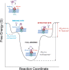
Fig. 6. Illustration of the free-energy binding landscape of C5a binding to C5aR.
ΔGbu gives the free-energy difference between the ligand-bound and unbound states and is indicated for each binding site (binding site, effector site, and binding site + effector site) by vertical arrows. A positive allosteric interaction is measured when both binding sites (binding site and effector site) are occupied, as revealed by a significantly higher ΔGbu for the full binding of the C5a.

References

    1. Ward PA. The dark side of C5a in sepsis. Nat. Rev. Immunol. 2004;4:133. doi: 10.1038/nri1269. - DOI - PubMed
    1. Woodruff TM, Nandakumar KS, Tedesco F. Inhibiting the C5–C5a receptor axis. Mol. Immunol. 2011;48:1631–1642. doi: 10.1016/j.molimm.2011.04.014. - DOI - PubMed
    1. Klos A, Wende E, Wareham KJ, Monk PN. International Union of Basic and Clinical Pharmacology. LXXXVII. Complement peptide C5a, C4a, and C3a receptors. Pharmacol. Rev. 2013;65:500–543. doi: 10.1124/pr.111.005223. - DOI - PubMed
    1. Guo R-F, Ward PA. Role OF C5a in inflammatory responses. Ann. Rev. Immunol. 2005;23:821–852. doi: 10.1146/annurev.immunol.23.021704.115835. - DOI - PubMed
    1. Siciliano SJ, et al. Two-site binding of C5a by its receptor: an alternative binding paradigm for G protein-coupled receptors. Proc. Natl Acad. Sci. USA. 1994;91:1214–1218. doi: 10.1073/pnas.91.4.1214. - DOI - PMC - PubMed

Publication types