Emergency ventilator for COVID-19
- PMID: 33378363
- PMCID: PMC7773325
- DOI: 10.1371/journal.pone.0244963
Emergency ventilator for COVID-19
Abstract
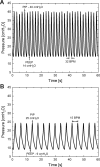
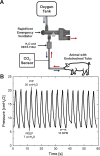
The COVID-19 pandemic disrupted the world in 2020 by spreading at unprecedented rates and causing tens of thousands of fatalities within a few months. The number of deaths dramatically increased in regions where the number of patients in need of hospital care exceeded the availability of care. Many COVID-19 patients experience Acute Respiratory Distress Syndrome (ARDS), a condition that can be treated with mechanical ventilation. In response to the need for mechanical ventilators, designed and tested an emergency ventilator (EV) that can control a patient's peak inspiratory pressure (PIP) and breathing rate, while keeping a positive end expiratory pressure (PEEP). This article describes the rapid design, prototyping, and testing of the EV. The development process was enabled by rapid design iterations using additive manufacturing (AM). In the initial design phase, iterations between design, AM, and testing enabled a working prototype within one week. The designs of the 16 different components of the ventilator were locked by additively manufacturing and testing a total of 283 parts having parametrically varied dimensions. In the second stage, AM was used to produce 75 functional prototypes to support engineering evaluation and animal testing. The devices were tested over more than two million cycles. We also developed an electronic monitoring system and with automatic alarm to provide for safe operation, along with training materials and user guides. The final designs are available online under a free license. The designs have been transferred to more than 70 organizations in 15 countries. This project demonstrates the potential for ultra-fast product design, engineering, and testing of medical devices needed for COVID-19 emergency response.
Conflict of interest statement
The study was funded by University of Illinois Urbana-Champaign and by Carle Foundation Hospital. GD is principal at Tekmill Inc., which worked on the project at the direction of and under contract to the University of Illinois Urbana-Champaign. SE, AM, and BR are employees of Creative Thermal Solutions Inc., which worked on the project at the direction of and under contract to the University of Illinois Urbana-Champaign. DB, MN, JO, SR, and CW are employees at Fast Radius Inc., which worked on the project at the direction of and under contract to the University of Illinois Urbana-Champaign. WPK is Professor at University of Illinois Urbana-Champaign and Chief Scientist at Fast Radius Inc., which manufactured prototypes used in this study. WPK performed the work in as an employee at the University of Illinois Urbana-Champaign and received no compensation from Fast Radius. This project was conducted in accordance with conflict of management policies at both organizations. This does not alter our adherence to PLOS ONE policies on sharing data and materials. There are no other patents, products in development or marketed products associated with this research to declare.
Figures


References
-
- World Health Organization. Novel Coronavirus (2019-nCoV) Situation Report—1. 2020. Available: https://www.who.int/emergencies/diseases/novel-coronavirus-2019/situatio...
-
- WHO Director-General’s opening remarks at the media briefing on COVID-19–11 March 2020. 2020 [cited 6 Apr 2020]. Available: https://www.who.int/dg/speeches/detail/who-director-general-s-opening-re...
-
- World Health Organization. Coronavirus disease 2019 (COVID-19) Situation Report—51. 2020. Available: https://www.who.int/emergencies/diseases/novel-coronavirus-2019
-
- Maslov S, Goldenfeld N. Flattening the curve fails unless done very early: results from a simulation of ICU capacity in Chicago. 2020. Available: guava.physics.uiuc.edu/~nigel/REPRINTS/2020/v3.4 ICU estimates for Chicago 3-18-2020.pdf%0D
Publication types
MeSH terms
LinkOut - more resources
Full Text Sources
Medical

