Camouflage treatment for skeletal Class III patient with facial asymmetry using customized bracket based on CAD/CAM virtual orthodontic system
- PMID: 33378502
- PMCID: PMC8028456
- DOI: 10.2319/102318-768.1
Camouflage treatment for skeletal Class III patient with facial asymmetry using customized bracket based on CAD/CAM virtual orthodontic system
Abstract
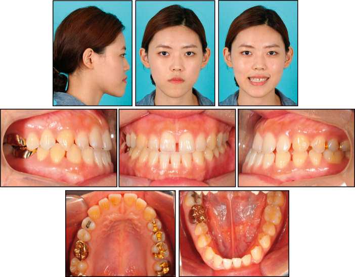
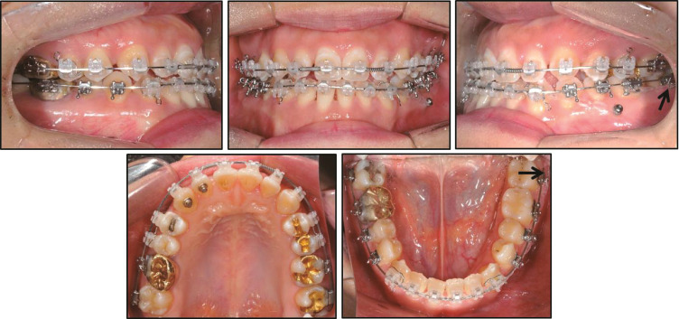
When considering camouflage orthodontic treatment for Class III malocclusion with skeletal facial asymmetry, it is crucial to preserve the favorable compensated posterior occlusion. Once the inclination of the compensated occlusion is changed during orthodontic treatment, unstable occlusion, such as crossbite or scissor bite may occur. A 23-year-old female patient had anterior spacing with Class III malocclusion and a mandibular asymmetry. A nonsurgical approach was adopted. The treatment objectives were to establish a Class I molar relationship with compensated inclination of the posterior dentition and to correct the midline deviation. To achieve these goals, the computer-aided design/computer-aided manufacturing (CAD/CAM) orthodontic system plus customized brackets was applied, and miniscrews were used to distalize the left mandibular dentition for midline correction. The results suggested that the CAD/CAM-based customized brackets can be efficiently used in camouflage treatment to achieve a correct final occlusion.
Keywords: Camouflage treatment; Class III malocclusion; Customized bracket.
© 2000 by the EH Angle Education and Research Foundation, Inc.
Figures


Similar articles
-
Surgical treatment of a skeletal Class III patient using customized brackets based on the CAD/CAM virtual orthodontic system.Angle Orthod. 2021 Sep 1;91(5):692-704. doi: 10.2319/060820-528.1. Angle Orthod. 2021. PMID: 33566066 Free PMC article.
-
Nonsurgical correction of a Class III malocclusion in an adult by miniscrew-assisted mandibular dentition distalization.Am J Orthod Dentofacial Orthop. 2013 Jun;143(6):877-87. doi: 10.1016/j.ajodo.2012.05.021. Am J Orthod Dentofacial Orthop. 2013. PMID: 23726338
-
Favourable dentoalveolar changes after lower premolar extractions for Class III camouflage with completely customized lingual appliances.Head Face Med. 2024 Oct 11;20(1):57. doi: 10.1186/s13005-024-00459-5. Head Face Med. 2024. PMID: 39394608 Free PMC article.
-
The Mechanical and Clinical Properties of Customized Orthodontic Bracket Systems-A Comprehensive Review.J Funct Biomater. 2024 Oct 7;15(10):299. doi: 10.3390/jfb15100299. J Funct Biomater. 2024. PMID: 39452597 Free PMC article. Review.
-
Mandibular asymmetry: literature review and case report.Braz J Otorhinolaryngol. 2012 Jul-Aug;78(4):137. doi: 10.1590/S1808-86942012000400028. Braz J Otorhinolaryngol. 2012. PMID: 22936154 Free PMC article. Review. No abstract available.
Cited by
-
Scanning Accuracy of Bracket Features and Slot Base Angle in Different Bracket Materials by Four Intraoral Scanners: An In Vitro Study.Materials (Basel). 2021 Jan 13;14(2):365. doi: 10.3390/ma14020365. Materials (Basel). 2021. PMID: 33451075 Free PMC article.
-
Mechanical properties of CAD/CAM-fabricated in comparison to conventionally fabricated functional regulator 3 appliances.Sci Rep. 2021 Jul 19;11(1):14719. doi: 10.1038/s41598-021-94237-x. Sci Rep. 2021. PMID: 34282228 Free PMC article.
-
Skeletal Class III Malocclusion with Lateral Open Bite and Facial Asymmetry Treated with Asymmetric Lower Molar Extraction and Lingual Appliance: A Case Report.Int J Environ Res Public Health. 2021 May 18;18(10):5381. doi: 10.3390/ijerph18105381. Int J Environ Res Public Health. 2021. PMID: 34070132 Free PMC article.
-
Clinical effectiveness of customized versus noncustomized orthodontic appliances: A systematic review.J Orthod Sci. 2024 Sep 17;13:26. doi: 10.4103/jos.jos_46_24. eCollection 2024. J Orthod Sci. 2024. PMID: 39450227 Free PMC article. Review.
-
Comparison of six different CAD/CAM retainers vs. the stainless steel twistflex retainer: an in vitro investigation of survival rate and stability.J Orofac Orthop. 2025 Mar;86(2):119-128. doi: 10.1007/s00056-023-00486-y. Epub 2023 Jun 28. J Orofac Orthop. 2025. PMID: 37378840 Free PMC article.
References
-
- Ahn J, Kim SJ, Lee JY, Chung CJ, Kim KH. Transverse dental compensation in relation to sagittal and transverse skeletal discrepancies in skeletal Class III patients. Am J Orthod Dentofacial Orthop. 2017;151:148–156. - PubMed
-
- Song HK, Son WS, Park SB, Kim SS, Kim YI. The assessment of dentoalveolar compensation in facial asymmetry individuals: integration of cone beam CT and laser scanned dental cast images. Korean J Orthod. 2010;40:373–382.
-
- Burstone CJ. Diagnosis and treatment planning of patients with asymmetries. Semin Orthod. 1998;4:153–164. - PubMed
-
- Kai R, Umeki D, Sekiya T, Nakamura Y. Defining the location of the dental midline is critical for oral esthetics in camouflage orthodontic treatment of facial asymmetry. Am J Orthod Dentofacial Orthop. 2016;150:1028–1038. - PubMed
Publication types
MeSH terms
LinkOut - more resources
Full Text Sources
Miscellaneous