Review
. 2020 Dec;10(6):1874-1894.
doi: 10.21037/cdt-20-617.

Chest radiography of contemporary trans-catheter cardiovascular devices: a pictorial essay

Affiliations
Review

Chest radiography of contemporary trans-catheter cardiovascular devices: a pictorial essay

Subha Ghosh et al. Cardiovasc Diagn Ther. 2020 Dec.

Abstract

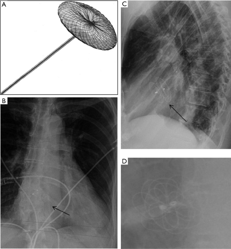
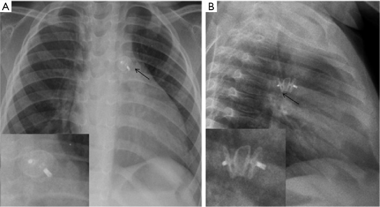
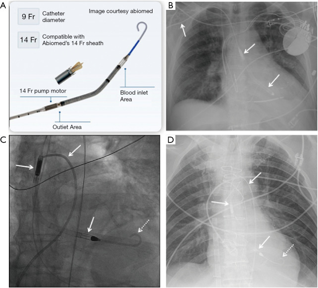
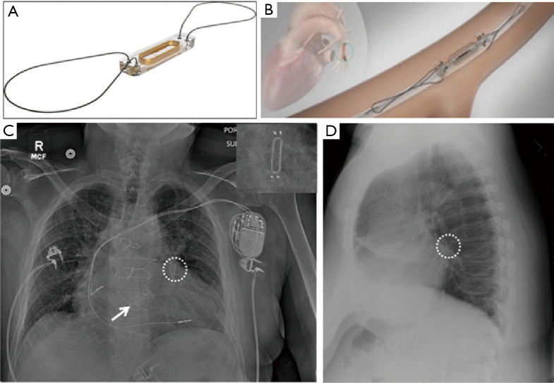
There is a plethora of cardiovascular devices used for therapy and monitoring, and newer devices are being introduced constantly. As a result of advancement of medical technology and rapid development of such technology to address unmet needs across cardiovascular care, multiple conditions which were previously treated surgically or with medications now benefit from trans-catheter device-based evaluation and management. Moreover, innovation to existing technology has transformed the structural design of many traditional cardiovascular devices, making them safer and enabling easier deployment within the chest (catheter-based versus surgical). A post-procedure chest radiography (CXR) is often the first routine imaging test ordered in these patients. A CXR is a relatively inexpensive and noninvasive imaging tool, which can be obtained at the patient's bedside if needed. Commonly implanted cardiovascular devices can be quite easily checked for appropriate positioning on routine CXRs. Potential complications associated with mal-positioning of such devices may be life-threatening. Such complications often manifest early on CXRs and may not be readily apparent on clinical examination. Prompt recognition of such abnormal radiographic appearances is critical for timely diagnosis and effective management. Clinicians need to be familiar with new devices in order to assess proper placement and identify complications related to mal-positioning. This pictorial essay aims to describe the radiologic appearances of contemporary cardiovascular devices, review indications for their usage and potential complications, and discuss magnetic resonance imaging (MRI) compatibility.

Keywords: Cardiovascular devices; chest radiography (CXR); trans-catheter.


Conflict of interest statement

Conflicts of Interest: All authors have completed the ICMJE uniform disclosure form (available at http://dx.doi.org/10.21037/cdt-20-617). The authors have no conflicts of interest to declare.

Figures

Figure 1
Figure 1
Radiographically-detectable post-procedure complications. (A) Right pneumothorax (asterisks). (B) Pneumomediastinum (arrows). (C) Pneumopericardium (arrows). (D) Pleural effusions due to intrapleural hemorrhage (asterisks). (E) Mediastinal widening due to mediastinal hematoma (arrows). (F) Pericardial effusion (enlarged cardiac silhouette, arrows).
Figure 2
Figure 2
Sapien 3, CoreValve, and Portico transcatheter aortic valves. (A) Photograph shows the Sapien 3 valve. (B) Frontal and (C) lateral radiographs show the Sapien 3 valve (arrow) in the expected aortic position. (D) Photograph shows the CoreValve. (E) Frontal and lateral (F) radiographs show the implanted CoreValve (arrow) in the expected aortic valve position. (G) Photograph shows the Portico valve.
Figure 3
Figure 3
Melody TPVR device. (A) Photograph shows the Melody TPVR device (Image courtesy Medtronic). (B) Frontal chest radiograph shows a melody TPVR device in the expected pulmonic position.
Figure 4
Figure 4
MitraClip. (A) Photograph of the MitraClip device shows the device size and the adjacent illustrated diagram of the LVOT shows the mitral valve and seated device (Image courtesy Abbott). (B) Frontal chest radiograph shows MitraClips (arrows) that are projected side by side parallel to one another over the expected position of the mitral valve and appropriately positioned. (C) Axial CT image of the same patient shows the clips causing metallic artefacts (arrow) over the mitral valve leaflets. (D) Frontal chest radiograph shows MitraClips (arrows) that have been used for tricuspid regurgitation and project over the midline tricuspid location. TAVR is also noted (dashed arrow).
Figure 5
Figure 5
Amplatzer Septal Occluder. (A) Photograph shows the device with self-expanding nitinol mesh (Image courtesy St Jude Medical). (B) Frontal, (C) lateral and (D) magnified chest radiographs show the device (arrow) projected over the expected location of the interatrial septum.
Figure 6
Figure 6
PDA occluder/Amplatzer duct occluder II Additional Sizes (ADO II AS). (A) Frontal and (B) lateral chest radiographs show the device (arrow) over the expected location of the aorto-pulmonary window with magnified images (inserts) that show the discs with tightly woven mesh.
Figure 7
Figure 7
Coarctation of aorta treated with stent. (A) Frontal chest radiograph shows the stent (curved arrow) in the expected position of proximal descending aorta. (B) Frontal chest radiograph with magnified image (insert) in a different patient shows the stent (arrow) projected in the expected location.
Figure 8
Figure 8
Parachute ventricular partitioning device. (A) Frontal chest radiograph shows the parachute device in the left ventricular apex with wire struts (arrows). (B) Axial CT image at the level of the device shows the wires (arrows) within the aneurysmal left ventricle apex. (C) Photograph and illustration show the device, the nitinol frame, and the ideal positioning of the device at the cardiac apex (image courtesy CardioKinetics).
Figure 9
Figure 9
Impella. (A) Impella design with parts. The device draws blood from the LV through the impeller with outflow into the ascending aorta. Similar device (Impella RP) can be used for right-sided or biventricular failure with inflow in the inferior vena cava and outflow tip within the main PA. (B) Frontal chest radiograph shows Impella placed via the right axillary artery with its tip in the left ventricle (LV) (arrows). (C,D) Digital radiograph at the time of insertion (C) and frontal chest radiograph post insertion (D) show placement of Impella (arrows) via the femoral approach. This is inserted percutaneously via the femoral artery, and passed retrograde through the aorta and aortic valve into the left ventricle (LV). Tip of the Impella should project centrally over the LV (dashed arrows).
Figure 10
Figure 10
IABP. (A) Frontal chest radiograph shows IABP inserted via the femoral artery with radio-opaque marker tip projected in the proximal descending thoracic aorta in a satisfactory position (dashed arrow). Note, the inflated balloon which appears as a midline long segment lucency below the radiopaque marker (black arrows), is usually not visualized on CXR. It inflates during diastole (promotes coronary filling) and deflates during systole (promotes forward flow). Note asymmetric lucency along the left costophrenic sulcus (white arrow) suggestive of left pneumothorax (“deep sulcus sign”). (B) Frontal chest radiograph shows IABP tip is too far distal and projects above the roof of the aortic arch (arrow), possibly wedged inside the lumen of the proximal left common carotid artery. This should be retracted to prevent intimal damage to the artery and potential stroke. Note, a Swan-Ganz catheter inserted via the femoral vein with its tip in the left pulmonary artery (dashed arrows). (C,D) Contrast-enhanced chest CT shows IABP with tip in the mid-descending thoracic aorta (arrow in C) and balloon inflated just above the diaphragmatic hiatus (arrow in D). This is a suboptimal position and risks mesenteric ischemia due to intermittent occlusion of the celiac and superior mesenteric arteries. (E) Frontal chest radiograph shows IABP inserted via the left axillary artery with marker projected just below the roof of the aortic arch and introducer sheath in the left axillary/subclavian region (arrows). Note, a Swan-Ganz catheter is also present with its tip in the right pulmonary artery (dashed arrows). (F) Chest CT shows the introducer/sheath in the left axillary/subclavian artery and balloon of the IABP (air lucency) in the left subclavian artery (arrows). Note, the radiopaque tip of the Swan-Ganz catheter in the right pulmonary artery (dashed arrows). IABP, intra-aortic balloon pump.
Figure 11
Figure 11
ECMO. (A) Frontal chest radiograph shows VV ECMO with a single wide bore venous cannula which has been inserted via the left subclavian vein, traverses the SVC and right atrium with its tip in the IVC (arrows). (B) Frontal chest radiograph shows VV ECMO with 2 separate cannulas, one inserted via the right internal jugular vein with tip in the upper right atrium and the other inserted via the femoral vein with tip in the mid right atrial cavity (arrows). Note dense bilateral airspace consolidations compatible with diffuse alveolar damage. (C) Frontal chest radiograph shows VA ECMO with venous limb inserted via the right internal jugular vein and arterial limb anastomosed to the aorta (arrows). Note also the presence of an Impella inserted via the right axillary artery with tip in the LV (dashed white arrows), and a Swan-Ganz catheter placed via the left subclavian vein with tip in the right pulmonary artery (dashed black arrows). ECMO, extra-corporeal membrane oxygenation cannulae.
Figure 12
Figure 12
Micra leadless pacemaker. (A) Frontal chest radiograph shows implantable leadless pacemaker (arrow) with magnified image (insert) projecting over the expected location for the device in the right ventricle. (B) Axial CT of a different patient at the level of the inter-ventricular septum shows the well-seated device in the right ventricle. (C) Frontal chest radiograph with magnified image (insert) and (D) lateral chest radiograph show the device in the expected right ventricle position (arrows) and internal fabric details in the magnified image. LAA ligation clip is noted (dashed arrows). LAA, left atrial appendage.
Figure 13
Figure 13
Loop recorder device. (A) Frontal and (B) lateral chest radiographs show the loop recorder device (arrow) which is similar to the leadless pacemaker device though easily differentiated on the lateral radiograph as the former projects within the subcutaneous chest wall. (C,D) Magnified images of the chest radiographs show different shapes and internal fabrics of the loop recorder devices.
Figure 14
Figure 14
CardioMEMS Heart Failure System. (A,B) Photographs show the CardioMEMS device (Image courtesy of St Jude Medical) and the illustrated image of the device inside the inferior left pulmonary artery. (C) Frontal chest radiograph shows the CardioMEMS device (dashed circle) over the left lower lobe pulmonary artery with magnified image (insert). TAVR is noted (arrow). (D) Lateral chest radiograph shows the CardioMEMS device (dashed circle) over the lower lobe pulmonary artery.
Figure 15
Figure 15
Bundle of His pacing lead. (A) Frontal and (B) lateral chest radiographs show a left chest wall cardiac defibrillator with 2 leads which terminate in the right ventricle and towards the Bundle of His. The Bundle of His lead is positioned towards the interventricular septum (arrow).
Figure 16
Figure 16
Watchman LAA closure device. (A) Photograph of a Watchman device shows the parachute shape and jellyfish-like appearance with nitinol frame (Image courtesy Boston Scientific). (B) Axial CT image shows the device in the expected position of LAA. (C) Frontal chest radiograph shows the LAA closure device (arrow) over the expected location of the LAA with magnified image (insert). (D) Lateral chest radiograph shows the LAA closure device (arrow) over the expected location of the LAA with magnified image (insert) and an anterior chest wall loop recorder (dashed arrows). LAA, left atrial appendage.
Figure 17
Figure 17
SVC and IVC filters. Frontal CXR shows an umbrella-shaped device with spokes in the expected location of the SVC with the pointed tip of the device directed towards the SVC-right atrial junction. A similar device is seen in the IVC with its tip directed towards the IVC-right atrial junction. CXR, chest radiography.

Similar articles

Cited by

References

    1. Fanari Z, Weintraub WS. Cost-effectiveness of transcatheter versus surgical management of structural heart disease. Cardiovasc Revasc Med 2016;17:44-7. 10.1016/j.carrev.2015.08.011 - DOI - PMC - PubMed
    1. Kapadia SR, Leon MB, Makkar RR, et al. 5-year outcomes of transcatheter aortic valve replacement compared with standard treatment for patients with inoperable aortic stenosis (PARTNER 1): a randomised controlled trial. Lancet 2015;385:2485-91. 10.1016/S0140-6736(15)60290-2 - DOI - PubMed
    1. Leon MB, Smith CR, Mack MJ, et al. Transcatheter or Surgical Aortic-Valve Replacement in Intermediate-Risk Patients. N Engl J Med 2016;374:1609-20. 10.1056/NEJMoa1514616 - DOI - PubMed
    1. Sigakis CJG, Mathai SK, Suby-Long TD, et al. Radiographic Review of Current Therapeutic and Monitoring Devices in the Chest. Radiographics 2018;38:1027-45. 10.1148/rg.2018170096 - DOI - PubMed
    1. Pasic M, Unbehaun A, Buz S, et al. Annular rupture during transcatheter aortic valve replacement: classification, pathophysiology, diagnostics, treatment approaches, and prevention. JACC Cardiovasc Interv 2015;8:1-9. 10.1016/j.jcin.2014.07.020 - DOI - PubMed