. 2020 Dec 29;12(1):27.
doi: 10.3390/mi12010027.

Microfluidic Device with an Integrated Freeze-Dried Cell-Free Protein Synthesis System for Small-Volume Biosensing

Affiliations

Microfluidic Device with an Integrated Freeze-Dried Cell-Free Protein Synthesis System for Small-Volume Biosensing

Taishi Tonooka. Micromachines (Basel). .

Abstract

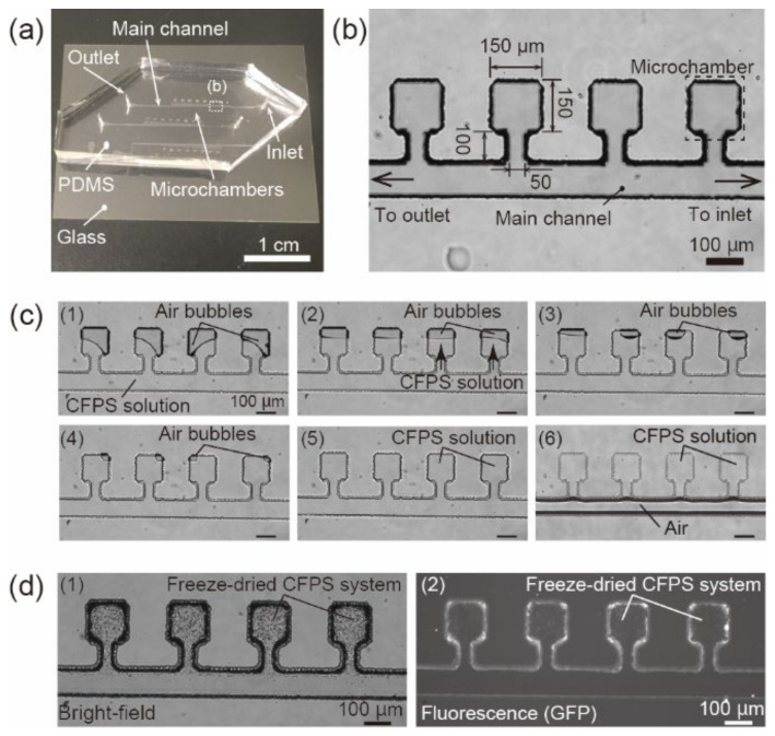
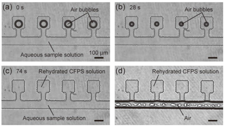
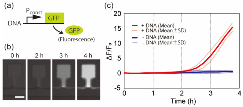
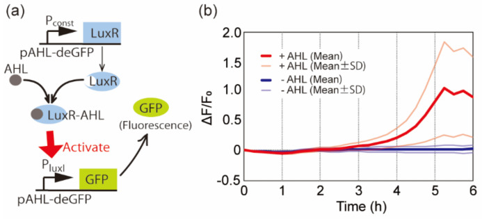
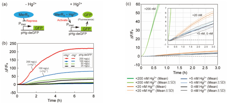
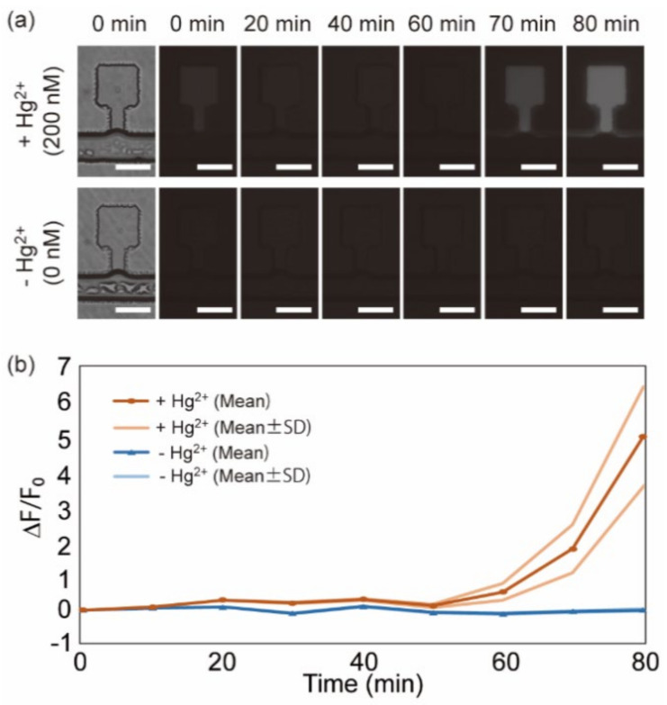
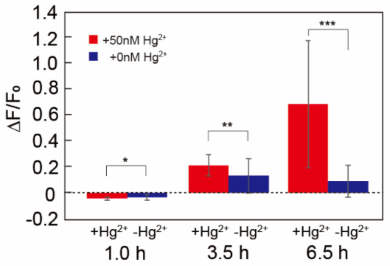
Microfluidic devices enable the precise operation of liquid samples in small volumes. This motivates why microfluidic devices have been applied to point-of-care (PoC) liquid biopsy. Among PoC liquid biopsy studies, some report diagnostic reagents being freeze-dried in such microfluidic devices. This type of PoC microfluidic device has distinct advantages, such as simplicity of the procedures, compared with other PoC devices using liquid-type diagnostic reagents. Despite the attractive characteristic, only diagnostic reagents based on the cloned enzyme donor immunoassay (CEDIA) have been freeze-dried in the microfluidic device. However, development of the PoC device based on the CEDIA method is time-consuming and labor-intensive. Here, we employed a molecule-responsive protein synthesis system as the diagnostic reagent to be freeze-dried in the microfluidic device. Such molecule-responsive protein synthesis has been well investigated in the field of molecular biology. Therefore, using the accumulated information, PoC devices can be efficiently developed. Thus, we developed a microfluidic device with an integrated freeze-dried molecule-responsive protein synthesis system. Using the developed device, we detected two types of bio-functional molecules (i.e., bacterial quorum sensing molecules and mercury ions) by injecting 1 µL of sample solution containing these molecules. We showed that the developed device is applicable for small-volume biosensing.

Keywords: cell-free protein synthesis (CFPS); freeze-dry; microfluidic device; point-of-care (PoC).


Conflict of interest statement

The author declares no conflict of interest.

Figures

Figure 1
Figure 1
Fabrication procedures of the microfluidic device integrated with the cell-free protein synthesis (CFPS) system. (a) Image of the whole microfluidic device. (b) Microscopic image of the microchambers in the microfluidic device. (c) Time-lapse microscopic images during the procedures to introduce the CFPS solution in the microchambers. (d) Bright-field image (d1) and fluorescent image (d2) of the freeze-dried CFPS system in the microchambers. The freeze-drying condition was ~10 mTorr, −20 °C, 3 h.
Figure 2
Figure 2
Rehydration of freeze-dried CFPS system in microchambers using an aqueous sample solution. (ac) Microscopic time-lapse images of the microchambers after injecting 1 μL of the aqueous sample solution from the inlet. (d) Microscopic images of the microchambers filled with the rehydrated CFPS solution. The freeze-drying condition was ~10 mTorr, −20 °C, 3 h.
Figure 3
Figure 3
Protein synthesis using freeze-dried CFPS system and freeze-dried DNA. (a) Schematic diagram of the gene circuit demonstrated in (b,c). (b) Time-lapse fluorescent images of the representative microchamber freeze-dried together with the DNA shown in (a). The scale bar is 100 µm. (c) Time-course of the fluorescent intensities in the microchambers with (+DNA) or without DNA (−DNA). SD shows standard deviation (n ≧ 3 each). The freeze-drying condition of the microfluidic device was ~30 mTorr, −80 °C, 6 h.
Figure 4
Figure 4
(a) Schematic diagram of N-acyl-homoserine-lactone (AHL) sensing using AHL-responsive DNA (pAHL-deGFP). (b) Time-course of the fluorescence intensities in the microchambers with the gene circuit shown in (a). The time interval between each image acquisition was 15 min. SD shows standard deviation (n ≧ 3 each). The freeze-drying condition of the microfluidic device was ~30 mTorr, −80 °C, 6 h.
Figure 5
Figure 5
Characterization of mercury sensing DNA (pHg-deGFP). (a) Schematic diagram of mercury sensing using the mercury sensing DNA. (b) Time-course of the fluorescent intensities of the CFPS solution with various pHg-deGFP concentrations. +Hg2+ and −Hg2+ represent the sample with/without 200 nM of Hg2+ respectively. (c) Time-course of the average fluorescent intensities of the CFPS solution with various Hg2+ concentrations. The CFPS solution contained 200 ng/μL of pHg-deGFP. The inset shows the magnified graph around ΔF/F0 = 0. Curves with the dark colors represent average (Mean). Curves with the light colors represent average ± standard deviation (n = 3) (Mean ± SD). The time interval between each data acquisition in (b,c) was 5 min.
Figure 6
Figure 6
Detection of mercury ions in the water sample. (a) Microscopic images of the representative microchambers with 200 nM of Hg2+ (upper row) and 0 nM of Hg2+ (lower row). Bright-field images at the initial state (left end) and time-lapse fluorescence images from 0 to 80 min. The exposure time was 5 s. The time interval between acquiring images was 10 min. The scale bars are 100 µm. (b) Time-course of the average relative fluorescence intensities in the microchambers with water containing 200 nM of Hg2+ (+Hg2+) or 0 nM of Hg2+ (−Hg2+). 200 ng/µL of pHg-deGFP was contained in the CFPS solution when freeze-drying. Curves with the dark colors represent average values (Mean). Curves with the light colors represent average ± standard deviation (n = 4) (Mean ± SD). The freeze-drying condition of the microfluidic device was ~10 mTorr, −20 °C, 3 h.
Figure 7
Figure 7
Detection of mercury ions in a water sample from the Kamo river. Average relative fluorescence intensities in the microchambers with river water containing 50 nM of Hg2+ (+50 nM Hg2+, red bars) and non-treated river water (+0 nM Hg2+, blue bars) after 1.0, 3.5, and 6.5 h. The river water sample with 50 nM of Hg2+ was prepared by dissolving HgCl2 into the river water. The water samples were injected in the microfluidic device at 0 h. Error bars represent standard deviation (n = 4). * p < 0.5, ** p < 0.5, *** p < 0.05 (Welch’s t-test) [25]. The freeze-drying condition of the microfluidic device was ~10 mTorr, −20 °C, 3 h.

Similar articles

Cited by

References

    1. Kulinsky L., Noroozi Z., Madou M. Present technology and future trends in point-of-care microfluidic diagnostics. Methods Mol. Biol. 2013;949:3–23. - PubMed
    1. Barbosa A.I., Reis N.M. A critical insight into the development pipeline of microfluidic immunoassay devices for the sensitive quantitation of protein biomarkers at the point of care. Analyst. 2017;142:858–882. doi: 10.1039/C6AN02445A. - DOI - PubMed
    1. Lazar I.M., Gulakowski N.S., Lazar A.C. Protein and Proteome Measurements with Microfluidic Chips. Anal. Chem. 2020;92:169–182. doi: 10.1021/acs.analchem.9b04711. - DOI - PMC - PubMed
    1. Ng A.H.C., Fobel R., Fobel C., Lamanna J., Rackus D.G., Summers A., Dixon C., Dryden M.D.M., Lam C., Ho M., et al. A digital microfluidic system for serological immunoassays in remote settings. Sci. Transl. Med. 2018;10:eaar6076. doi: 10.1126/scitranslmed.aar6076. - DOI - PubMed
    1. Nishiyama K., Sugiura K., Kaji N., Tokeshi M., Baba Y. Development of a microdevice for facile analysis of theophylline in whole blood by a cloned enzyme donor immunoassay. Lab Chip. 2019;19:233–240. doi: 10.1039/C8LC01105B. - DOI - PubMed

LinkOut - more resources