. 2020 Dec 18;9(13):31.
doi: 10.1167/tvst.9.13.31. eCollection 2020 Dec.

Oculomotor Responses to Dynamic Stimuli in a 44-Channel Suprachoroidal Retinal Prosthesis

Affiliations

Oculomotor Responses to Dynamic Stimuli in a 44-Channel Suprachoroidal Retinal Prosthesis

Samuel A Titchener et al. Transl Vis Sci Technol. .

Abstract

Purpose: To investigate oculomotor behavior in response to dynamic stimuli in retinal implant recipients.

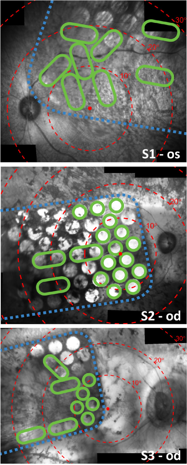
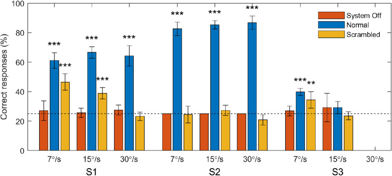
Methods: Three suprachoroidal retinal implant recipients performed a four-alternative forced-choice motion discrimination task over six sessions longitudinally. Stimuli were a single white bar ("moving bar") or a series of white bars ("moving grating") sweeping left, right, up, or down across a 42″ monitor. Performance was compared with normal video processing and scrambled video processing (randomized image-to-electrode mapping to disrupt spatiotemporal structure). Eye and head movement was monitored throughout the task.

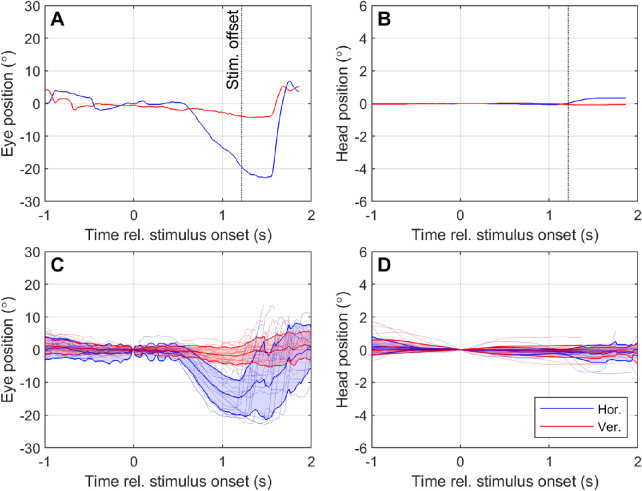
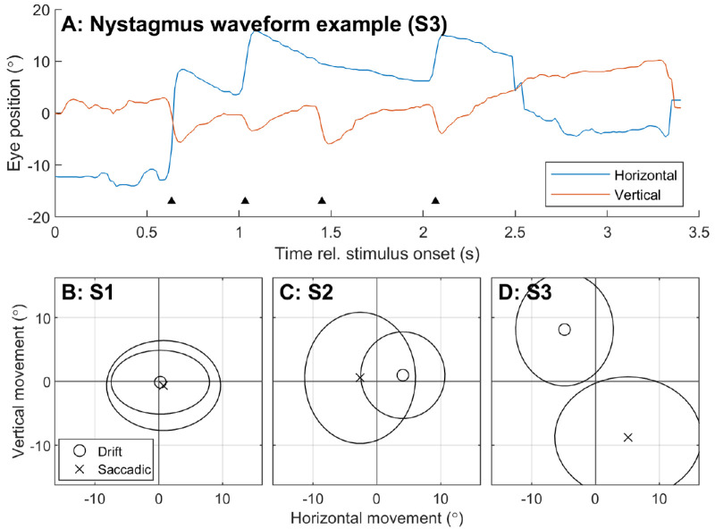
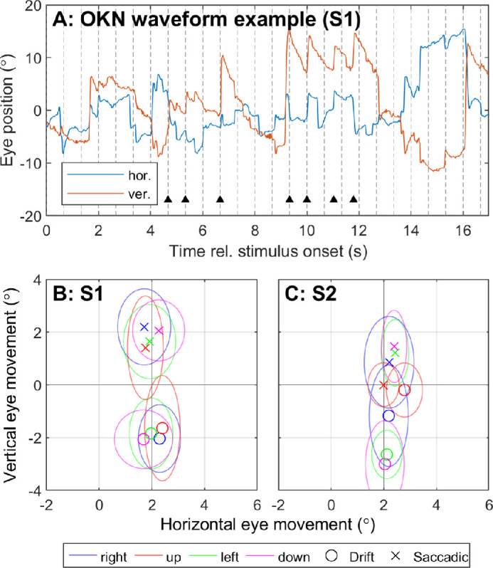
Results: Two subjects had diminished performance with scrambling, suggesting retinotopic discrimination was used in the normal condition and made smooth pursuit eye movements congruent to the moving bar stimulus direction. These two subjects also made stimulus-related eye movements resembling optokinetic reflex (OKR) for moving grating stimuli, but the movement was incongruent with stimulus direction. The third subject was less adept at the task, appeared primarily reliant on head position cues (head movements were congruent to stimulus direction), and did not exhibit retinotopic discrimination and associated eye movements.

Conclusions: Our observation of smooth pursuit indicates residual functionality of cortical direction-selective circuits and implies a more naturalistic perception of motion than expected. A distorted OKR implies improper functionality of retinal direction-selective circuits, possibly due to retinal remodeling or the non-selective nature of the electrical stimulation.

Translational relevance: Retinal implant users can make naturalistic eye movements in response to moving stimuli, highlighting the potential for eye tracker feedback to improve perceptual localization and image stabilization in camera-based visual prostheses.

Keywords: eye movements; head movements; motion perception; retinal prosthesis; visual prosthesis.


Conflict of interest statement

Disclosure: S.A. Titchener, Bionic Vision Technologies Pty Ltd (F); J. Kvansakul, Bionic Vision Technologies Pty Ltd (F); M.N. Shivdasani (P); J.B. Fallon, None; D.A.X. Nayagam, Bionic Vision Technologies Pty Ltd (F, P); S.B. Epp, Bionic Vision Technologies Pty Ltd (F); C.E. Williams, Bionic Vision Technologies Pty Ltd (F, P); N. Barnes, Bionic Vision Technologies Pty Ltd (F); W.G. Kentler, None; M. Kolic, Bionic Vision Technologies Pty Ltd (F); E.K. Baglin, Bionic Vision Technologies Pty Ltd (F); L.N. Ayton, None; C.J. Abbott, Bionic Vision Technologies Pty Ltd (F); C.D. Luu, Bionic Vision Technologies Pty Ltd (F, P); P.J. Allen, Bionic Vision Technologies Pty Ltd (F, P); M.A. Petoe, Bionic Vision Technologies Pty Ltd (F, P)

Figures

Figure 1.
Figure 1.
Stitched composite infrared fundus images (Spectralis; Heidelberg Engineering) showing the placement of the array on the retina for S1 (top, 17 weeks after surgery), S2 (middle, eight weeks after surgery), and S3 (bottom, eight weeks after surgery). Electrodes are visible in the images as bright circles. Note that some electrodes are obscured from view due to pigmentation. Dashed blue lines trace the edge of the implant. Red dots indicate the estimated location of the fovea and concentric red circles indicate 10° eccentricities of visual field according to the Drasdo and Fowler schematic eye., Green circles signify electrodes that were included in the subject's unique stimulus configuration, which was kept constant for all tasks and settings during the clinical trial. Larger green ovals indicate that two electrodes were operated as a shorted pair. Electrodes that are not circled in green were excluded from the stimulus configuration and were therefore not stimulated during the motion discrimination task. Some optical distortion and stitching artefact is expected.
Figure 2.
Figure 2.
Percent of correct responses for each subject in the moving bar task. Bars represent score pooled across all sessions. Error bars represent the standard error of the mean of the score per session. Data are separated by the speed at which the stimulus moved and by the image processing condition (normal, scrambled, system off). The horizontal dotted line specifies the chance rate of 25%. Asterisks denote above-chance performance for data pooled across sessions (binomial test, **P < 0.01, ***P < 0.001).
Figure 3.
Figure 3.
Example of eye and head responses to moving stimuli for participant S1. Panels A and B respectively display the eye and head movement during a single trial in which a 30°/s left-moving stimulus was presented. Panels C and D respectively display the average (± SD) eye and head movement over all trials in which a 30°/s left-moving stimulus was presented and correctly identified. Eye and head position are measured relative to the position at stimulus onset (t = 0). Positive values on the y-axis indicate rightwards horizontal movement (blue lines) or upward vertical movement (red lines). Note that the y-axis scale is different for head movement (B, D) compared to eye movement (A, C) because head movement was minimal.
Figure 4.
Figure 4.
Polar plots displaying the angular error between the direction of motion of the stimulus and the average ΔEyedrift and ΔHead for all subjects in the Normal and Scrambled conditions for 7°/s (blue), 15°/s (red), and 30°/s (yellow) stimuli. Each vector represents the mean direction and magnitude of the eye or head movement relative to the direction of motion of the stimulus. Vectors pointing approximately rightward (0°) indicate that on average the eye or head movement was in the same direction as the stimulus (for all stimulus directions). Asterisks indicate mean eye or head movement was significantly different to zero (Hotelling's one sample t-test with Bonferroni correction for multiple comparisons; *P < 0.05, **P < 0.01, ***P < 0.001). Hollow markers denote mean eye/head movements that were not significantly different to zero, indicating little movement or nonsystematic movement.
Figure 5.
Figure 5.
Characterization of baseline acquired nystagmus for each subject using eye movement during the moving bar task in the system off condition. Data was pooled across all stimulus speeds. (A) Example of a nystagmic waveform in S3. Black triangles indicate the beat (saccadic component) of the nystagmus. (B–D) Mean ΔEyedrift (circle markers) is compared to mean ΔEyesaccadic (crosses) for each participant. Ellipses indicate standard deviation. Slow and fast phase movements with opposing polarity indicate a beating nystagmus. S1 had no notable nystagmus, S2 exhibited a left-beat nystagmus, and S3 exhibited a down-beat nystagmus.
Figure 6.
Figure 6.
Characterization of nystagmus for S1 and S2 in the moving grating task. (A) Example of a nystagmic waveform observed in S1 during the moving grating task. (B, C) Mean ΔEyedrift (circle markers) is compared to mean ΔEyesaccadic (crosses) for each stimulus direction for each participant. Color represents the direction of motion of the stimulus. Ellipses indicate standard deviation. Slow and fast phase movements with opposing polarity indicate a beating nystagmus. Both participants exhibited up-beat nystagmus in response to the moving grating stimuli, regardless of stimulus direction. Only data for 30°/s, 20° pitch are shown.

References

    1. Luo YH-L, da Cruz L. The Argus II Retinal Prosthesis System. Prog Retin Eye Res. 2016; 50: 89–107. - PubMed
    1. Edwards TL, Cottriall CL, Xue K, et al. .. Assessment of the electronic retinal implant alpha AMS in restoring vision to blind patients with end-stage retinitis pigmentosa. Ophthalmology. 2018; 125(3): 432–443. - PMC - PubMed
    1. Muqit MMK, Velikay-Parel M, Weber M, et al. .. Six-month safety and efficacy of the Intelligent Retinal Implant System II device in retinitis pigmentosa. Ophthalmology. 2019; 126(4): 637–639. - PubMed
    1. Palanker D, Le Mer Y, Mohand-Said S, Muqit MMK, Sahel JA. Photovoltaic restoration of central vision in atrophic age-related macular degeneration. Ophthalmology. 2020; 127(8): 1097–1104. - PMC - PubMed
    1. Beauchamp MS, Oswalt D, Sun P, et al. .. Dynamic stimulation of visual cortex produces form vision in sighted and blind humans. Cell. 2020; 181(4): 774–783.e5. - PMC - PubMed

Publication types