. 2021 Mar:228:117696.
doi: 10.1016/j.neuroimage.2020.117696. Epub 2020 Dec 30.

Fast computational optimization of TMS coil placement for individualized electric field targeting

Affiliations

Fast computational optimization of TMS coil placement for individualized electric field targeting

Luis J Gomez et al. Neuroimage. 2021 Mar.

Abstract

Background: During transcranial magnetic stimulation (TMS) a coil placed on the scalp is used to non-invasively modulate activity of targeted brain networks via a magnetically induced electric field (E-field). Ideally, the E-field induced during TMS is concentrated on a targeted cortical region of interest (ROI). Determination of the coil position and orientation that best achieve this objective presently requires a large computational effort.

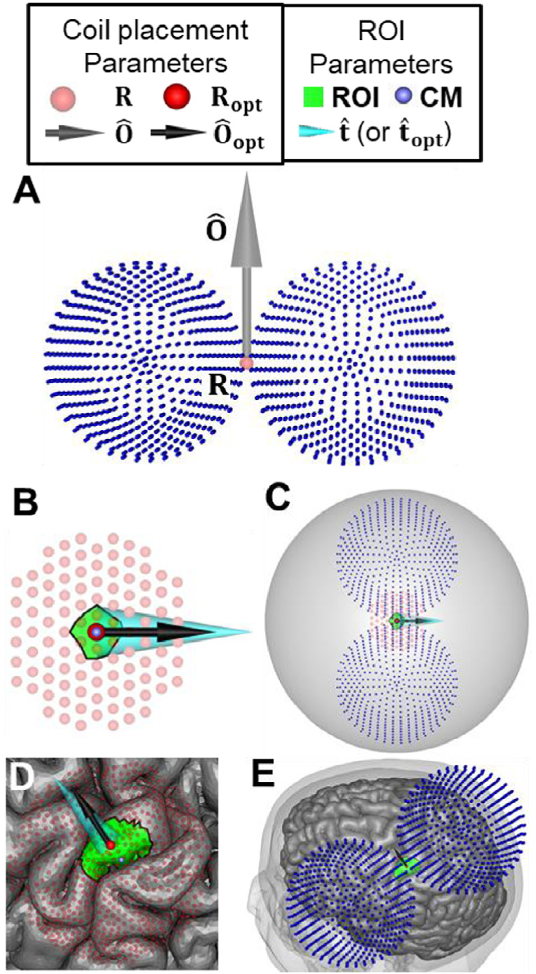
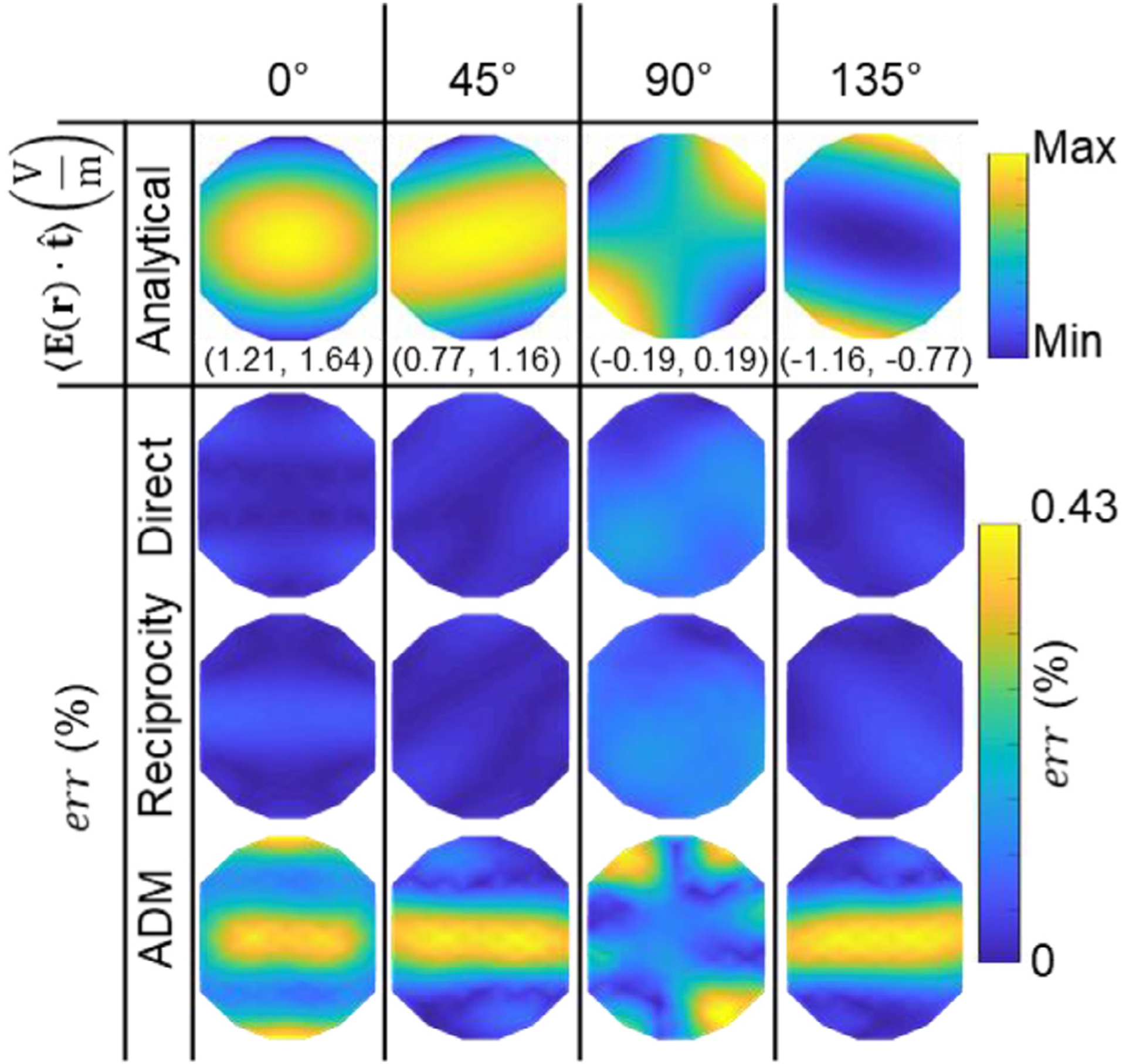
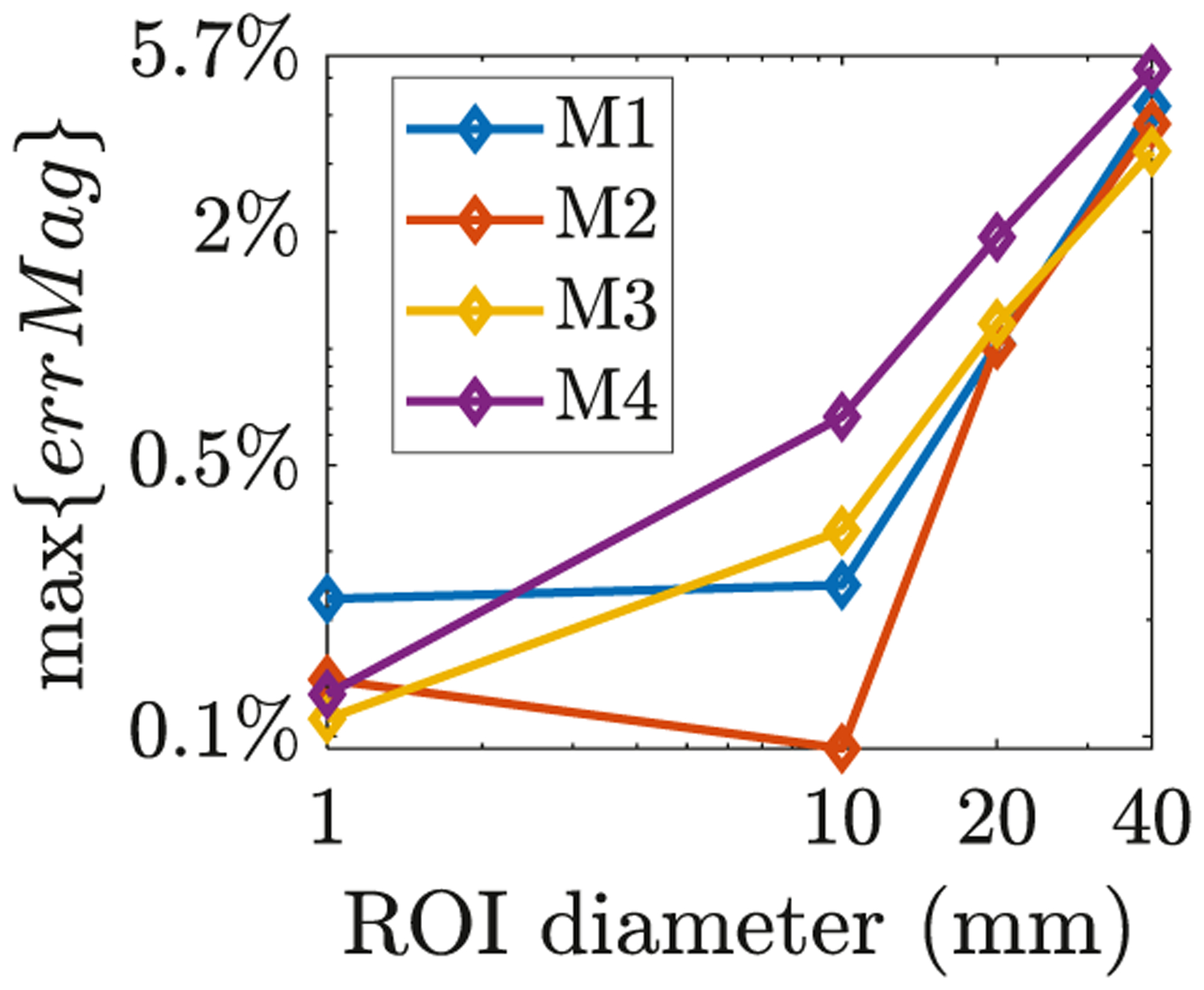
Objective: To improve the accuracy of TMS we have developed a fast computational auxiliary dipole method (ADM) for determining the optimum coil position and orientation. The optimum coil placement maximizes the E-field along a predetermined direction or, alternatively, the overall E-field magnitude in the targeted ROI. Furthermore, ADM can assess E-field uncertainty resulting from precision limitations of TMS coil placement protocols.

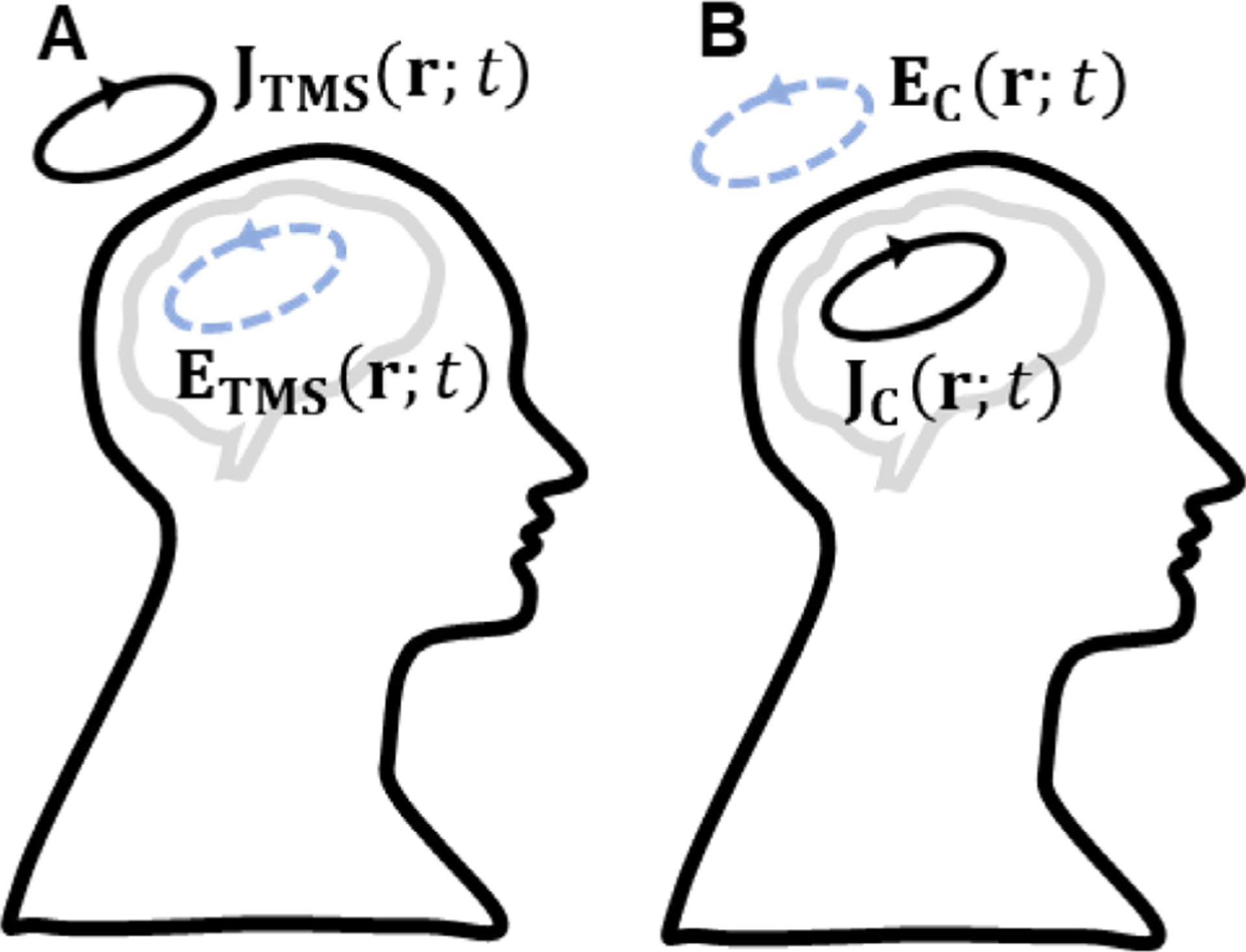
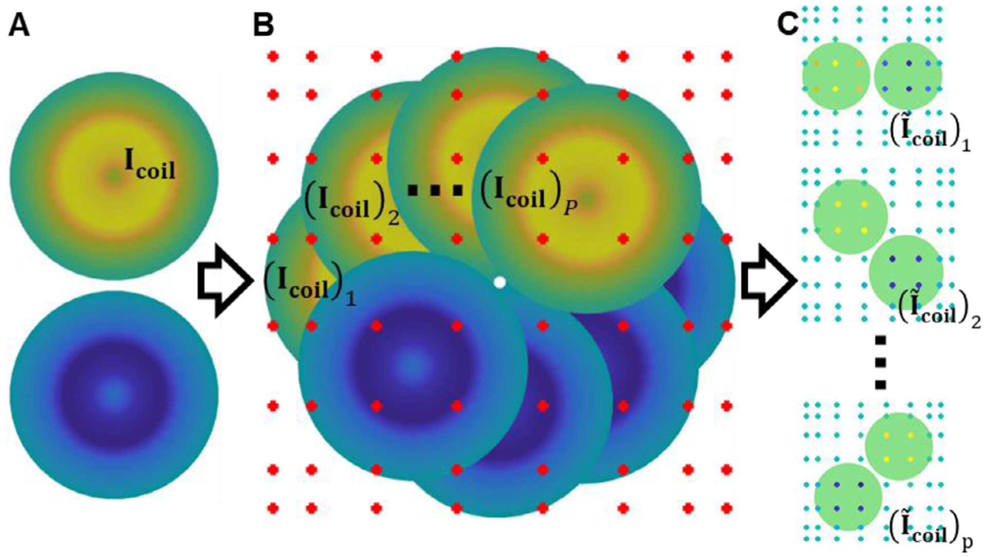
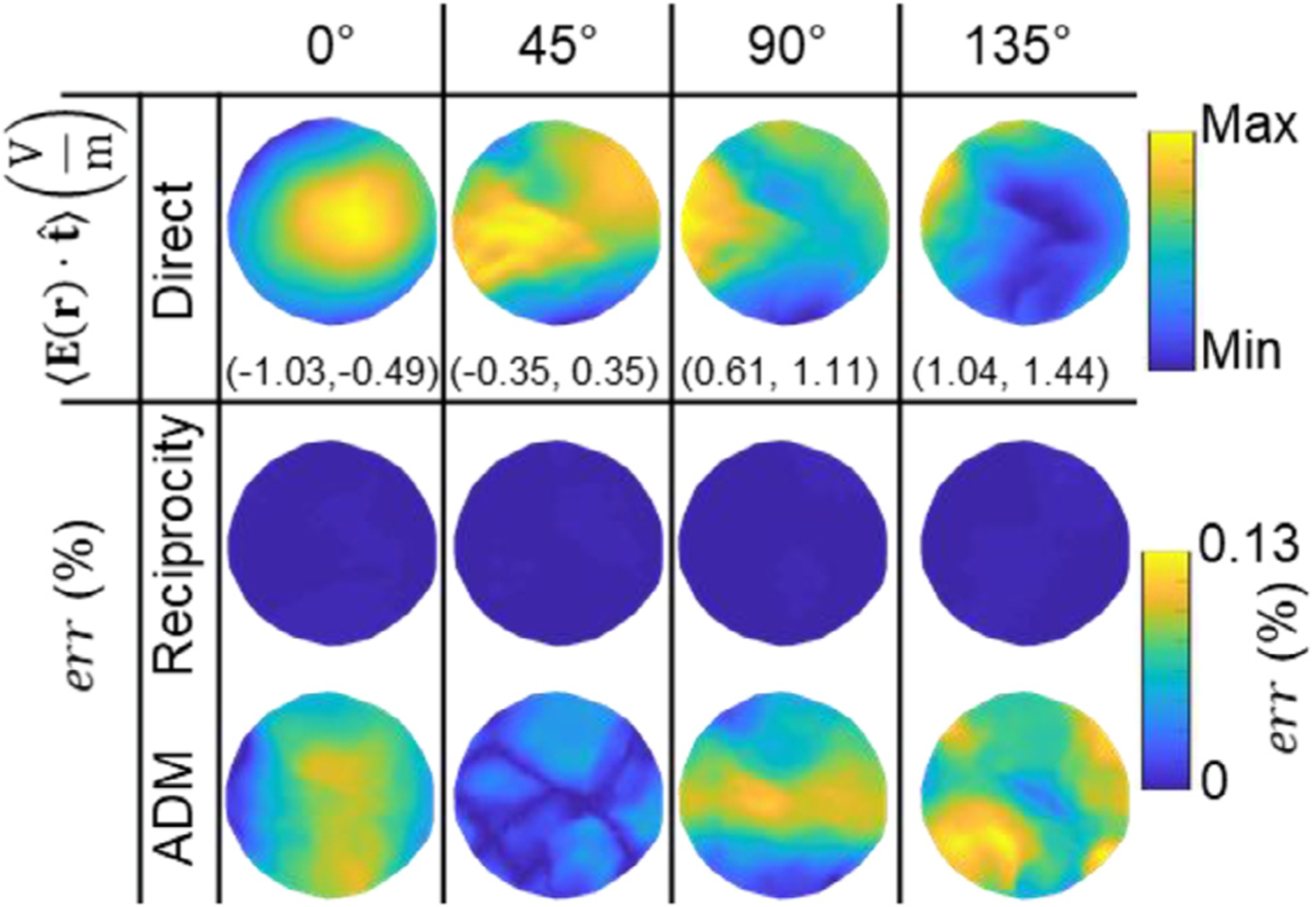
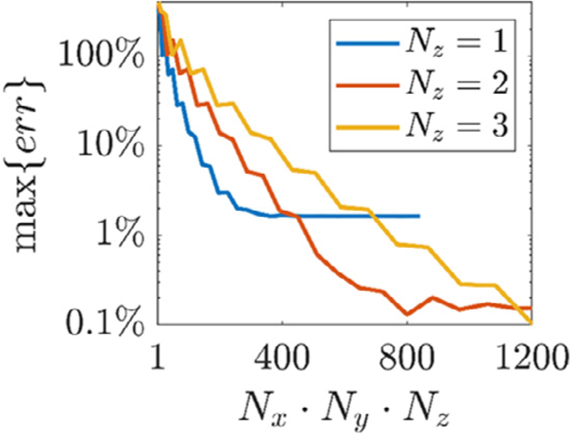
Method: ADM leverages the electromagnetic reciprocity principle to compute rapidly the TMS induced E-field in the ROI by using the E-field generated by a virtual constant current source residing in the ROI. The framework starts by solving for the conduction currents resulting from this ROI current source. Then, it rapidly determines the average E-field induced in the ROI for each coil position by using the conduction currents and a fast-multipole method. To further speed-up the computations, the coil is approximated using auxiliary dipoles enabling it to represent all coil orientations for a given coil position with less than 600 dipoles.

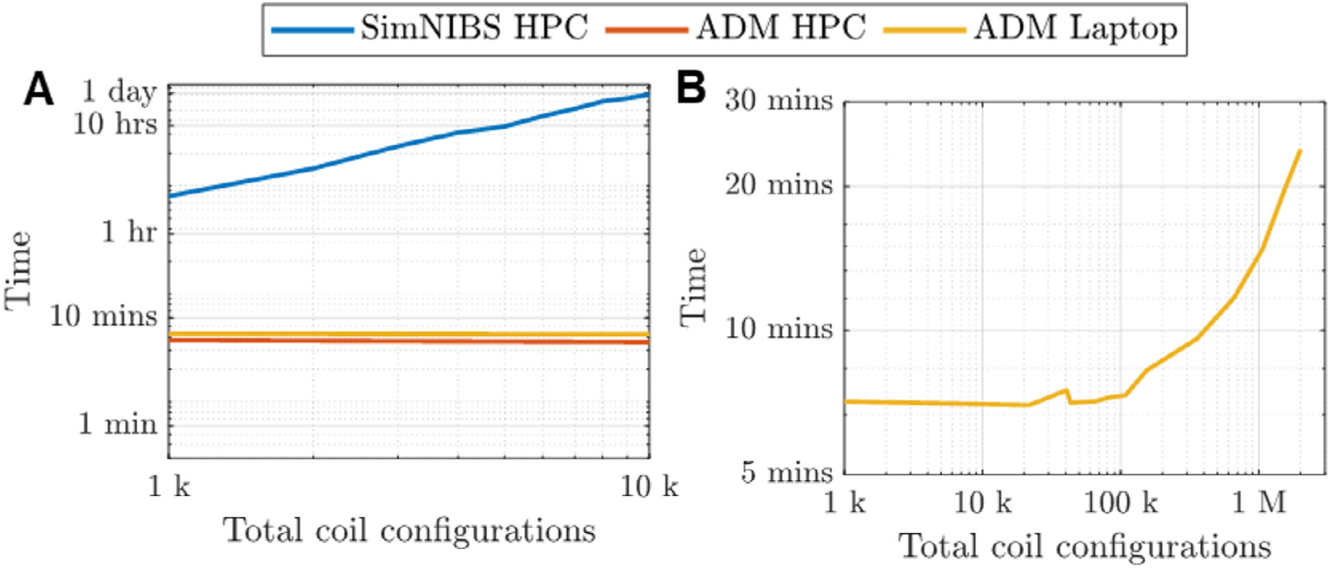
Results: Using ADM, the E-fields generated in an MRI-derived head model when the coil is placed at 5900 different scalp positions and 360 coil orientations per position (over 2.1 million unique configurations) can be determined in under 15 min on a standard laptop computer. This enables rapid extraction of the optimum coil position and orientation as well as the E-field variation resulting from coil positioning uncertainty. ADM is implemented in SimNIBS 3.2.

Conclusion: ADM enables the rapid determination of coil placement that maximizes E-field delivery to a specific brain target. This method can find the optimum coil placement in under 15 min enabling its routine use for TMS. Furthermore, it enables the fast quantification of uncertainty in the induced E-field due to limited precision of TMS coil placement protocols, enabling minimization and statistical analysis of the E-field dose variability.

Keywords: Auxiliary dipole method; Coil; E-field; Model; Optimal; Ranscranial magnetic stimulation; Reciprocity; TMS; Targeting.


Conflict of interest statement

Conflict of interest declaration A. V. Peterchev is inventor on patents and patent applications related to TMS and, in the past 3 years, has received travel funds as well as patent royalties from Rogue Research; research grants, travel funds, consulting fees, as well as equipment donation from Tal Medical / Neurex; research grant, hardware donations, and patent application support from Magstim; equipment loans and hardware donations from MagVenture; and consulting fees from Neuronetics, BTL Industries, and ACI.

Figures

Fig. 1.
Fig. 1.
Conventions for describing TMS coil placement in this paper. (A) Figure-8 coil placement is defined by position R and orientation O^ (the dipoles representing the coil model are shown as small dark blue spheres). (B) Dark and lighter red-colored spheres indicate candidate coil positions above the brain ROI colored in green. The ROI center of mass (CM) is indicated by a small purple sphere. The optimal coil position and orientation are indicated by a red sphere and black arrow, respectively. Wide cyan cone indicates either the preferred E-field direction t^ in the ROI, if it is specified, or the average E-field direction t^opt in the ROI resulting from maximization of the E-field magnitude. (C) For the spherical head model, the optimum coil position is directly above the ROI CM and its orientation is aligned exactly with the specified t^. (D,E) The same concepts illustrated for an MRI-based head model (Ernie). For such models, the optimum coil position and orientation can differ from CM and t^ (or t^opt), respectively.
Fig. 2.
Fig. 2.
Reciprocal scenarios: (A) The TMS coil current generates an E-field inside the brain. (B) A brain current source generates an E-field where the coil resides.
Fig. 3.
Fig. 3.
Auxiliary dipole method (ADM) work-flow. (A) TMS coil model consisting of M coil dipoles Icoil(i) each at location rcoil(i). (B) P TMS coil models (Icoil)i each with a different orientation and immersed in a grid of Gauss-Legendre nodes. (C) Magnitude of dipole weights (I˜coil)j for P individual coil orientations: warm and cold colors represent positive and negative values, respectively.
Fig. 4.
Fig. 4.
Validation of the computational methods in sphere head model. The 1st row shows, as a reference, the analytically computed average ROI E-field in direction t^ (oriented horizontally) across TMS coil positions on the scalp. The scalp area spanned by the coil positions has a diameter of 2 cm. Four coil orientations are considered, from left to right: 0°, 45°, 90°, and 135°. The range of observed E-field component values are given in parenthesis below each figure in V/m. The 2nd, 3rd, and 4th row contain the corresponding absolute error relative to the analytical solution, err, for the direct, reciprocity, and ADM methods, respectively.
Fig. 5.
Fig. 5.
Validation in the Ernie head model, analogous to Fig. 4. The 1st row shows, as a reference, the directly computed average ROI E-field in direction t^ (oriented horizontally) across TMS coil positions on the scalp. The scalp area spanned by the coil positions has a diameter of 2 cm. Four coil orientations are considered, from left to right: 0°, 45°, 90°, and 135°. The range of observed E-field component values are given in parenthesis below each figure in V/m. The 2nd and 3rd row contain the corresponding error relative to the direct method, err, for the reciprocity and ADM approaches, respectively. The direct method is used as a reference since there is no analytical solution for anatomically-detailed MRI-based head models.
Fig. 6.
Fig. 6.
Maximum normalized absolute error for ADM relative to the reciprocity results as a function of number of ADM auxiliary dipoles Nx · Ny · Nz.
Fig. 7.
Fig. 7.
Maximum E-field magnitude estimate error (Eq. (9)) using ADM compared to the reciprocity results as a function of ROI diameter.
Fig. 8.
Fig. 8.
CPU runtime versus number of total coil position and orientation configurations. (A) Results for SimNIBS 3.1 direct method and ADM run on a high performance computation system (HPC) and a laptop (ADM only). (B) Extended results for ADM. CPU runtimes are averaged across models M1–M4.
Fig. 9.
Fig. 9.
Coil placements maximizing the average E-field magnitude in ROIs of various size in models M1–M4 (left to right columns). (A)–(D): Illustration of the ADM-optimized coil placement for the 10 mm diameter ROI in models M1–M4, respectively. (E)–(T): Position and orientation optimized with the SimNIBS direct method and ADM are represented by pink and orange arrow, respectively, t^opt and the ROI CM are represented by cyan cone and purple sphere, respectively. Rows, top to bottom, show results for increasing ROI diameter of 1, 10, 20, and 40 mm. In most cases both optimization methods result in the same or similar coil position and orientation.
Fig. 10.
Fig. 10.
Comparisons of induced average E-field magnitude (A–C) and coil position (D–F) for ROIs of various sizes across different coil positioning strategies: (A,D) SimNIBS 3.1 optimization versus a placement over ROI CM; (B,E) ADM optimization versus ROI CM placement; (C,F) ADM versus SimNIBS 3.1. Additional coil optimization comparisons are given in Tables S1 and S2 in the supplemental material.
Fig. 11.
Fig. 11.
Coil position uncertainty results for model M2 and 10 mm diameter ROI. (A) Coil placements are chosen on the scalp above the brain ROI. The coil is oriented along the white vector and orientation uncertainty is always chosen as θ Δ = 10°. The support of coil position uncertainty for RΔ = 2.5 mm, RΔ = 5.0 mm, and RΔ = 10 mm is marked by the orange, black, and magenta circles, respectively. The maximum of the expected value and standard deviation for the average E-field along t^ for each coil position is determined. (B–D) The standard deviation assuming a coil position uncertainty of (B) 2.5 mm, (C) 5 mm, and (D) 10 mm. (E–G) The expected value for the average E-field assuming a coil position uncertainty RΔ of (E) 2.5 mm, (F) 5 mm, and (G) 10 mm. Results are normalized by the maximum expected average E-field over all coil positions and orientations.
Fig. 12.
Fig. 12.
90% confidence region of marginal distributions and expected value of the average E-field along t^ in the ROI as a function of coil position and orientation uncertainty. (A–E) Results for θ Δ = 10° and the coil positioned (A) centered or (B–E) 5 mm off-center relative to the ROI. (F) Results for R Δ = 5 mm and the coil centered above the ROI.

References

    1. Aberra AS, Wang B, Grill WM, Peterchev AV, 2020. Simulation of transcranial magnetic stimulation in head model with morphologically-realistic cortical neurons. Brain Stimul. 13, 175–189. - PMC - PubMed
    1. Balderston NL, Roberts C, Beydler EM, Deng ZD, Radman T, Luber B, Lisanby SH, Ernst M, Grillon C, 2020. A generalized workflow for conducting electric field-optimized, fMRI-guided, transcranial magnetic stimulation. Nat. Protoc 15, 3595–3614. - PMC - PubMed
    1. Balslev D, Braet W, McAllister C, Miall RC, 2007. Inter-individual variability in optimal current direction for transcranial magnetic stimulation of the motor cortex. J. Neurosci. Methods 162, 309–313. - PubMed
    1. Barker AT, Jalinous R, Freeston IL, 1985. Non-invasive magnetic stimulation of human motor cortex. Lancet 325, 1106–1107. - PubMed
    1. Beynel L, Davis S, Crowell C, Hilbig S, Lim W, Nguyen D, Palmer H, Brito A, Peterchev A, Luber B, 2019. Online repetitive transcranial magnetic stimulation during working memory in younger and older adults: a randomized within-subject comparison. PLoS ONE 14. - PMC - PubMed

Publication types