. 2021 Jan 11:10:e62691.
doi: 10.7554/eLife.62691.

Stochastic asymmetric repartition of lytic machinery in dividing CD8+ T cells generates heterogeneous killing behavior

Affiliations

Stochastic asymmetric repartition of lytic machinery in dividing CD8+ T cells generates heterogeneous killing behavior

Fanny Lafouresse et al. Elife. .

Abstract

Cytotoxic immune cells are endowed with a high degree of heterogeneity in their lytic function, but how this heterogeneity is generated is still an open question. We therefore investigated if human CD8+ T cells could segregate their lytic components during telophase, using imaging flow cytometry, confocal microscopy, and live-cell imaging. We show that CD107a+-intracellular vesicles, perforin, and granzyme B unevenly segregate in a constant fraction of telophasic cells during each division round. Mathematical modeling posits that unequal lytic molecule inheritance by daughter cells results from the random distribution of lytic granules on the two sides of the cleavage furrow. Finally, we establish that the level of lytic compartment in individual cytotoxic T lymphocyte (CTL) dictates CTL killing capacity.

Keywords: cell division; cytotoxic t lymphocytes; human; human lymphocytes; immunology; inflammation; lysosomal-associated membrane proteins; lytic granules.


Conflict of interest statement

FL, RJ, SM, MD, VD, EE, MP, SG, SV No competing interests declared

Figures
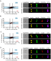
Figure 1.
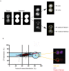
Figure 1.. Lytic components are asymmetrically distributed in dividing CD8+ T cells.
(A–C) Freshly isolated polyclonal CD8+ T cells or (D) CTL clones were stimulated by immobilized anti-CD8/anti-CD28/ICAM-1 during 72 hr and stained with antibodies directed against the indicated markers. Cells in telophase were identified using imaging flow cytometry. (A) Left panel: Each dot represents one nascent daughter cell. Only one of the two nascent daughter cells in telophase is plotted. The percentage of staining for CD107a in the presented cell (x axis) is plotted against the percentage of staining for total cell proteins (CTV, y axis). Asymmetric cells were defined as cells in telophase in which repartition of CD107a in the nascent daughter cells was beyond the 40–60% observed for CTV repartition (n = 908 from three independent experiments). Right panel: Example of asymmetric and symmetric cell distribution of CD107a, as detected by imaging flow cytometry. (B) Left panel: The percentage of staining for perforin in the presented nascent daughter cell is plotted as in (A). Asymmetric cells were defined as indicated in (A) (n = 191 from three independent experiments). Right panel: Example of asymmetric and symmetric cell distribution of perforin. (C) Left panel: The percentage of staining for GrzB in the presented nascent daughter cell is plotted as in (A). Asymmetric cells were defined as indicated in (A) (n = 728 from two independent experiments). Right panel: Example of asymmetric and symmetric cell distribution of GrzB. (D) Left panel: The percentage of staining for CD107a is plotted as in (A). Asymmetric cells were defined as indicated in (A) (n = 352 from three independent experiments). Right panel: Example of asymmetric and symmetric cell distribution of CD107a. Numbers highlighted in blue in the plots indicate the percentage of cells exhibiting asymmetric repartition of the marker of interest. Red lines indicate the global distribution of the data. Red numbers indicate the slope of the linear regression curve for marker distribution. See Figures S1, S2, S3, and S4.
Figure 1—figure supplement 1.
Figure 1—figure supplement 1.. Gating strategy for imaging flow cytometry (IsX) acquisition.
Based on the brightfield illumination, all events were plotted for their aspect ratio (length/width, equal one for perfectly round cells) and their area. Cells in telophase were defined as those exhibiting a low aspect ratio and a big area. The region of interest (gray) included cell doublets and cells in anaphase and telophase. Based on the intensity of DNA staining (represented in linear axis), cells in G2/M were selected. We then applied a mask on the IsX image gallery (as described in Materials and methods) to define the limits of the nuclei. This strategy was used to determine the number of nuclei present in each gated cell. To unambiguously identify cells in telophase, we applied a mask on α-tubulin staining allowing to detect condensed microtubules in an elongated shape (as described in Materials and methods). This procedure allowed us to detect the midbody (a structure characteristic of telophase formed by highly condensed α-tubulin that bridges the two nascent daughter cells). Cells included the described gates were finally visually inspected. All the cells recognized as in telophases on the basis of nuclear and tubulin staining were included in the analysis of the markers of interest.
Figure 1—figure supplement 2.
Figure 1—figure supplement 2.. Analysis and representation of the repartition of markers of interest in dividing cells.
(A) Analysis of individual cells in telophase. All IsX generated TIFF files were analyzed using the Fiji software. For each telophase cell, we used three TIFF image corresponding to (1) CTV staining, (2) α-tubulin staining, and (3) marker of interest. To standardize analysis, we used macro programming on Fiji (described in Supplementary results section). To determine a rupture zone between the two nascent daughter cells, we applied watershed function on tubulin mask. The watershed masks were used to determine the two nascent daughter cells in which the fluorescence intensities of CTV and of the markers of interest were measured (yellow lines). (B) Example of a cell exhibiting asymmetric distribution in telophase of a marker of interest. The yellow lines highlight the nascent daughter cell exhibiting a higher content of the marker of interest.
Figure 1—figure supplement 3.
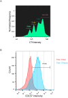
Figure 1—figure supplement 3.. CD8+ T cells are efficiently stimulated on coated anti-CD3/anti-CD28/ICAM1.
Freshly isolated polyclonal CD8+ T cells previously stained with CTV were stimulated 72 hr using immobilized anti-CD3/anti-CD28/ICAM1. (A) Imaging flow cytometry shows that stimulated cell undergo several rounds of division as shown by CTV staining dilution. (B) Flow cytometry shows upregulation of CD137 expression in stimulated cells.
Figure 1—figure supplement 4.
Figure 1—figure supplement 4.. Uneven lytic granule segregation in telophase in CD8+ memory T cells.
The panels show staining for CD107a and perforin in human CD8+ memory T cells stimulated and analyzed as in Figure 1A,B. CD107a n = 978 from three independent experiments; perforin n = 1127 from three independent experiments. Numbers highlighted in blue in the plots indicate the percentage of cells exhibiting asymmetric repartition of the marker of interest. Red lines indicate the global distribution of the data. Red numbers indicate the slope of the linear regression curve for marker distribution.
Figure 2.
Figure 2.. CD107a+ vesicle uneven segregation in telophase is confirmed by confocal laser scanning microscopy.
Freshly isolated polyclonal CD8+ T cells were stimulated by immobilized anti-CD8/anti-CD28/ICAM-1 during 72 hr and stained with antibodies directed against CD107a. Cells in telophase were identified using confocal laser scanning microscopy. (A) Analysis of CD107a repartition in dividing cells. The fold increase of CD107a staining in the brighter nascent daughter cell as compared to the other nascent daughter cell is shown. The dotted red line indicates the limit between symmetric and asymmetric cells (1.5 fold increase, corresponding to a 60–40% variation) (n = 61 from two independent experiments). Each dot represents one CD8+ T cell in telophase. (B) Example of an asymmetric cell in division. Green CD107a, cyan DAPI, red Tubulin. A maximum intensity projection (MIP) of a z-stack of images (left panel) and one z-section (right panel) are shown. See Figure 2—video 1.
Figure 3.
Figure 3.. Fate determining transcription factors do not undergo uneven distribution in telophase.
Freshly isolated polyclonal CD8+ T cells were stimulated by immobilized anti-CD8/anti-CD28/ICAM-1 during 72 hr and stained with antibodies directed against T-bet (A) or c-Myc (B). (A) T-bet analysis (n = 926 from three independent experiments). (B) c-Myc analysis (n = 703 from three independent experiments). Numbers highlighted in blue in the plots indicate the % of cells exhibiting asymmetric repartition of the marker of interest. Red lines indicate the global distribution of the data. Red numbers indicate the slope of the linear regression curve for marker distribution.
Figure 4.
Figure 4.. A polarity cue is not necessary for asymmetric repartition of lytic machinery.
(A) Freshly isolated polyclonal CD8+ T cells were stimulated using immobilized anti-CD8/anti-CD28/ICAM-1 (left) or with PMA/ionomycin (right) during 72 hr and stained with antibodies directed against CD107a. Each dot represents one nascent daughter cell. Only one of the two nascent daughter cells in telophase that were identified by Imaging Flow Cytometry is plotted. The percentage of staining for CD107a in the presented nascent daughter cell (x axis) is plotted against the percentage of staining for total cell proteins (CTV, y axis). Asymmetric cells were defined as in Figure 1. Left: CD107a analysis when cells were stimulated with immobilized stimuli (n = 1185 from three independent experiments). Right: CD107a analysis when cells were stimulated with PMA/ionomycin (n = 644 from three independent experiments). Numbers highlighted in blue in the plots indicate the % of cells exhibiting asymmetric repartition of the marker of interest. Red lines indicate the global distribution of the data. Red numbers indicate the slope of the linear regression curve for CD107a distribution. (B) Histograms represent the mean and standard deviation of the percentage of asymmetric cells in the three independent experiments. No statistical difference was revealed by paired t-test.
Figure 5.
Figure 5.. Asymmetric repartition of CD107a+ vesicles resets at each division event.
(A, B) Freshly isolated polyclonal CD8+ T cells were stimulated using immobilized anti-CD8/anti-CD28/ICAM-1 during 72 hr and stained with antibodies directed against CD107a. Cells in telophase were identified by imaging flow cytometry. The number of divisions accomplished and the cell cycle phase were determined on the basis of CTV and SYTOX nuclear staining. (A) Each dot represents one nascent daughter cell. Only one of the two nascent daughter cells in telophase that were identified by imaging flow cytometry is plotted. The percentage of staining for CD107a in the presented nascent daughter cell (x axis) is plotted against the percentage of staining for total cell proteins (CTV, y axis). Asymmetric cells were defined as in Figure 1. Numbers highlighted in blue in the plots indicate the % of cells exhibiting asymmetric repartition of the marker of interest. Red lines indicate the global distribution of the data. Red numbers indicate the slope of the linear regression curve for CD107a distribution. See Figure S3. (B) Histograms represent the mean and standard deviation of the percentage of asymmetric cells in three independent experiments. No statistical difference was revealed by paired t-test. (C, D) Statistical analysis of cells in telophase and in G1. (C) Cells in telophase are plotted against their CD107a FI. The different curves represent cells having undergone zero, one, or two mitoses. Each dot indicates one cell undergoing asymmetric CD107a repartition as compared to its CD107a FI. The χ2 statistical test showed that cells undergoing uneven repartition of lytic machinery in telophase were randomly distributed all over the CD107a expression curves (See Materials and methods). (D) Plots show cells in G1 from three different experiments. Curves represent the distribution of CD107a florescence intensity for all cells in G1. Individual plots, marked with different colors, show cells in G1 at different rounds of division. The Kolmogorov–Smirnov goodness-of-fit test rejected the hypothesis that the CD107a expression curves follow the same distribution at the different division round (see Supplementary Results). The χ2 test showed that variability was distributed all over the curves. See Figure S3.
Figure 6.
Figure 6.. Lytic granules randomly distribute on the two sides of the cleavage furrow.
(A,B) Snapshots depict typical cells in division undergoing even (A) or uneven (B) repartition of lytic granules (mCherry-tagged GrzB, red) in telophase as detected by live-cell imaging. Images are from Figure 6—videos 1 and 2, respectively. Results are from three independent experiments. (C,D) Snapshots depict Imaris software reconstructions of typical cells undergoing even (C) or uneven (D) repartition of LTR+ (red) lytic granules in division as detected by 4D live-cell imaging. Images are from Figure 6—videos 3 and 4, respectively. Results are from four independent experiments. See Figure 6—videos 3–5. (E) Binomial modeling for the behavior of the population of n granules. The curve shows the probability of lytic granule asymmetric repartition in telophase as a function of lytic granule number. (F) Monte-Carlo simulation of particle correlation as a function of lytic granule number and probability of lytic granule asymmetric repartition.
Figure 6—figure supplement 1.
Figure 6—figure supplement 1.. Lysotracker randomly distribute on the two sides of the cleavage furrow.
(A,B) Snapshots depict Imaris software reconstructions of typical cells undergoing uneven (A) and even (B) repartition of LTR+ (red) lytic granules in division as detected by 4D live-cell imaging. Images are from Figure 6—video 5.
Figure 7.
Figure 7.. CTL expressing high level of lytic granules have better killing capability.
Clonal CTL were FACS sorted on the basis of their LysoTracker Blue staining. (A) Representative FACS histograms showing LysoTracker Blue staining levels on LysoTrackerhigh and LysoTrackerlow sorted CTL at the indicated day (D) after cell sorting. Numbers indicate mean fluorescence intensity. Results are representative of three independent experiments (B,C) LysoTrackerHigh and LysoTrackerLow CTL-mediated cytotoxicity was evaluated by FACS analysis by measuring 7-AAD uptake in target cells either pulsed or not with antigenic peptide following overnight incubation with CTL at the indicated E/T ratio. (B) Cytotoxicity is expressed as the % of 7-AAD+-pulsed target cells minus % of 7-AAD+-unpulsed target cells (basal). Results are from three independent experiments. Each dot represents results from one experiment performed in triplicate. Means ± SEM are shown. Paired t-tests were performed, and p-values are indicated. (C) Histograms shown are from one representative experiment. Numbers indicate the percentage of 7-AAD-positive target cells. (D) LysoTrackerHigh and LysoTrackerLow CTL CD107a exposure after a 4 hr incubation with target cells pulsed or not with antigenic peptide (E/T ratio 0.5:1) was evaluated by FACS analysis. Each dot represents results from four independent experiments performed either in duplicate or triplicate. Means ± SEM are shown. Paired t-tests were performed, and p-values are indicated. (E) CD8 expression in LysoTrackerHigh and LysoTrackerLow CTL after a 4 hr incubation with target cells pulsed with antigenic peptide (E/T ratio: 0.5:1) was evaluated by FACS analysis. Results are normalized on CD8 MFI level of LysoTrackerHigh and LysoTrackerLow CTL cultured in the absence of target cells. Each dot represents results from four independent experiments performed either in duplicate or triplicate. Means ± SEM are shown.
Author response image 1.
Author response image 1.. CD107a fold increase measured by comparing the two nascent daughter cells in individual dividing CD8+ T cells (Figure 1A and 2A) and Lysotracker fold increase measured by comparing Lysotrackerhigh and Lysotrackerlow sorted CTL (Figure 7A).
Results are from the indicated figures of the revised manuscript. The red line indicates the 1.5 threshold for asymmetric repartition of CD107a (corresponding to the 40-60% range) between daughter cells. Numbers in blue indicate the percentage of individual telophasic cells exhibiting a CD107a fold increase higher than 1.5.

Similar articles

Cited by

References

    1. Arsenio J, Kakaradov B, Metz PJ, Kim SH, Yeo GW, Chang JT. Early specification of CD8+ T lymphocyte fates during adaptive immunity revealed by single-cell gene-expression analyses. Nature Immunology. 2014;15:365–372. doi: 10.1038/ni.2842. - DOI - PMC - PubMed
    1. Arsenio J, Metz PJ, Chang JT. Asymmetric cell division in T lymphocyte fate diversification. Trends in Immunology. 2015;36:670–683. doi: 10.1016/j.it.2015.09.004. - DOI - PMC - PubMed
    1. Basiji D, O'Gorman MR. Imaging flow cytometry. Journal of Immunological Methods. 2015;423:1–2. doi: 10.1016/j.jim.2015.07.002. - DOI - PubMed
    1. Bergeland T, Widerberg J, Bakke O, Nordeng TW. Mitotic partitioning of endosomes and lysosomes. Current Biology. 2001;11:644–651. doi: 10.1016/S0960-9822(01)00177-4. - DOI - PubMed
    1. Beuneu H, Lemaître F, Deguine J, Moreau HD, Bouvier I, Garcia Z, Albert ML, Bousso P. Visualizing the functional diversification of CD8+ T cell responses in lymph nodes. Immunity. 2010;33:412–423. doi: 10.1016/j.immuni.2010.08.016. - DOI - PubMed

Publication types