Review
. 2020 Nov 12;8(1):2002254.
doi: 10.1002/advs.202002254. eCollection 2020 Jan.

Approaches for Long Lifetime Organic Light Emitting Diodes

Affiliations
Review

Approaches for Long Lifetime Organic Light Emitting Diodes

Sujith Sudheendran Swayamprabha et al. Adv Sci (Weinh). .

Abstract

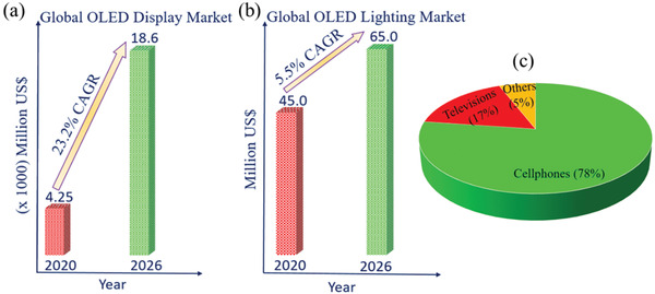
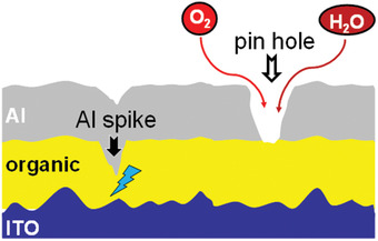
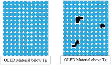
Organic light emitting diodes (OLEDs) have been well known for their potential usage in the lighting and display industry. The device efficiency and lifetime have improved considerably in the last three decades. However, for commercial applications, operational lifetime still lies as one of the looming challenges. In this review paper, an in-depth description of the various factors which affect OLED lifetime, and the related solutions is attempted to be consolidated. Notably, all the known intrinsic and extrinsic degradation phenomena and failure mechanisms, which include the presence of dark spot, high heat during device operation, substrate fracture, downgrading luminance, moisture attack, oxidation, corrosion, electron induced migrations, photochemical degradation, electrochemical degradation, electric breakdown, thermomechanical failures, thermal breakdown/degradation, and presence of impurities within the materials and evaporator chamber are reviewed. Light is also shed on the materials and device structures which are developed in order to obtain along with developed materials and device structures to obtain stable devices. It is believed that the theme of this report, summarizing the knowledge of mechanisms allied with OLED degradation, would be contributory in developing better-quality OLED materials and, accordingly, longer lifespan devices.

Keywords: OLED; degradation; device architecture; lifetime; materials.


Conflict of interest statement

The authors declare no conflict of interest.

Figures

Figure 1
Figure 1
Overview of OLED global market revenue by a) display and b) lighting application. c) Contribution of OLED technology by application in next‐generation electronic devices.
Figure 2
Figure 2
A brief history of OLED technology evolution.
Figure 3
Figure 3
Number of research articles on WOLED per year (Web of Science).
Figure 4
Figure 4
Highest power efficiency WOLED per year (Web of Science).
Figure 5
Figure 5
Number of research articles on blue OLED per year (Web of Science).
Figure 6
Figure 6
Highest power efficiency of blue OLED per year (Web of Science).
Figure 7
Figure 7
Number of research articles on red OLED per year (Web of Science).
Figure 8
Figure 8
Highest power efficiency of red OLED per year (Web of Science).
Figure 9
Figure 9
Number of papers of lifetime per year (Web of Science).
Figure 10
Figure 10
Illustrates the number of patents on WOLEDs filed per year (Web of Science).
Figure 11
Figure 11
Electrolysis of water molecules and formation of dark spots inside an OLED device.
Figure 12
Figure 12
The reaction of Alq3with moisture and oxygen[ 110 ]
Figure 13
Figure 13
Pinholes in metal layer causing device failure.
Figure 14
Figure 14
Molecular migration causing OLED device failure.
Figure 15
Figure 15
Atomic migration causing OLED device failure.
Figure 16
Figure 16
General schematic illustration of the influence of glass transition temperature (T g) in the thermal degradation of OLED materials.
Figure 17
Figure 17
High injection barrier generating high joule heat.
Figure 18
Figure 18
External dust particles causing formation of dark spots.
Figure 19
Figure 19
Molecular structures of heavy metal complexes based phosphorescent emitters.
Figure 20
Figure 20
Molecular structures of host materials using in both fluorescent and phosphorescent OLEDs.
Figure 21
Figure 21
Molecular structures of ETL materials using in OLEDs.
Figure 22
Figure 22
Molecular structures of TADF emitters using in OLEDs.
Figure 23
Figure 23
Molecular structures of TADF host materials using in OLEDs.
Figure 24
Figure 24
Molecular structures of HTL materials using in OLEDs.
Figure 25
Figure 25
Device architectures of step‐wise energy transfer in OLEDs.
Figure 26
Figure 26
Schematic representation of a two stack tandem OLED device.
Figure 27
Figure 27
Device architectures of conventional and p–i–n OLEDs.
Figure 28
Figure 28
General device structure of a) conventional and (b) inverted OLED device.
Figure 29
Figure 29
(Left) Schematic representation of excitons in conventional and exciplex OLEDs. (Right) Essential parameters for donor and acceptor to obtain TADF mechanism enabling exciplex forming cohost systems.

References

    1. Shahnawaz S., Sudheendran S. S., Nagar M. R., Yadav R. A. K., Gull S., Dubey D. K., Jou J.‐H., J. Mater. Chem. C 2019, 7, 7144.
    1. Rogers J. A., Someya T., Huang Y., Science 2010, 327, 1603. - PubMed
    1. Gather M. C., Köhnen A., Meerholz K., Adv. Mater. 2011, 23, 233. - PubMed
    1. Geffroy B., le Roy P., Prat C., Polym. Int. 2006, 55, 572.
    1. Buckley A., Organic Light‐Emitting Diodes (OLEDs): Materials, Devices and Applications, Elsevier, Amsterdam, The Netherlands: 2013.

LinkOut - more resources