

CMOS Image Sensors in Surveillance System Applications
- PMID: 33445557
- PMCID: PMC7827463
- DOI: 10.3390/s21020488
CMOS Image Sensors in Surveillance System Applications
Abstract
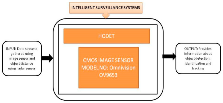
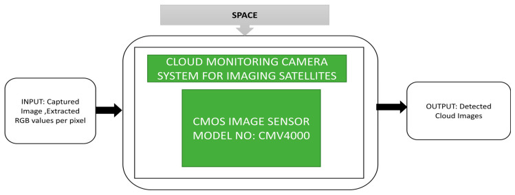
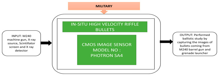
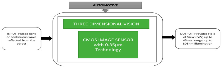
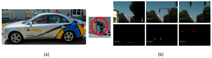
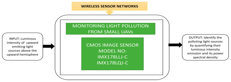
Recent technology advances in CMOS image sensors (CIS) enable their utilization in the most demanding of surveillance fields, especially visual surveillance and intrusion detection in intelligent surveillance systems, aerial surveillance in war zones, Earth environmental surveillance by satellites in space monitoring, agricultural monitoring using wireless sensor networks and internet of things and driver assistance in automotive fields. This paper presents an overview of CMOS image sensor-based surveillance applications over the last decade by tabulating the design characteristics related to image quality such as resolution, frame rate, dynamic range, signal-to-noise ratio, and also processing technology. Different models of CMOS image sensors used in all applications have been surveyed and tabulated for every year and application.
Keywords: CMOS image sensor; dynamic range; frame rate; resolution; signal-to-noise ratio; surveillance systems.
Conflict of interest statement
The authors declare no conflict of interest.
Figures


Similar articles
-
A Multi-Resolution Mode CMOS Image Sensor with a Novel Two-Step Single-Slope ADC for Intelligent Surveillance Systems.Sensors (Basel). 2017 Jun 25;17(7):1497. doi: 10.3390/s17071497. Sensors (Basel). 2017. PMID: 28672832 Free PMC article.
-
Neural Monitoring With CMOS Image Sensors.Basic Clin Neurosci. 2018 May-Jun;9(3):227-235. doi: 10.29252/NIRP.BCN.9.3.227. Basic Clin Neurosci. 2018. PMID: 30034653 Free PMC article.
-
Applications of the Integrated High-Performance CMOS Image Sensor to Range Finders - from Optical Triangulation to the Automotive Field.Sensors (Basel). 2008 Mar 13;8(3):1719-1739. doi: 10.3390/s8031719. Sensors (Basel). 2008. PMID: 27879789 Free PMC article.
-
Microhotplates for Metal Oxide Semiconductor Gas Sensor Applications-Towards the CMOS-MEMS Monolithic Approach.Micromachines (Basel). 2018 Oct 29;9(11):557. doi: 10.3390/mi9110557. Micromachines (Basel). 2018. PMID: 30715056 Free PMC article. Review.
-
CMOS Enabled Microfluidic Systems for Healthcare Based Applications.Adv Mater. 2018 Apr;30(16):e1705759. doi: 10.1002/adma.201705759. Epub 2018 Feb 27. Adv Mater. 2018. PMID: 29484725 Review.
Cited by
-
E2VIDX: improved bridge between conventional vision and bionic vision.Front Neurorobot. 2023 Oct 26;17:1277160. doi: 10.3389/fnbot.2023.1277160. eCollection 2023. Front Neurorobot. 2023. PMID: 37954492 Free PMC article.
-
A CMOS Image Sensor Dark Current Compensation Using In-Pixel Temperature Sensors.Sensors (Basel). 2023 Nov 10;23(22):9109. doi: 10.3390/s23229109. Sensors (Basel). 2023. PMID: 38005496 Free PMC article.
-
Two High-Precision Proximity Capacitance CMOS Image Sensors with Large Format and High Resolution.Sensors (Basel). 2022 Apr 4;22(7):2770. doi: 10.3390/s22072770. Sensors (Basel). 2022. PMID: 35408384 Free PMC article.
-
Investigating a Machine Learning Approach to Predicting White Pixel Defects in Wafers-A Case Study of Wafer Fabrication Plant F.Sensors (Basel). 2024 May 15;24(10):3144. doi: 10.3390/s24103144. Sensors (Basel). 2024. PMID: 38793997 Free PMC article.
-
Inverse design of color routers in CMOS image sensors: toward minimizing interpixel crosstalk.Nanophotonics. 2024 Jul 1;13(20):3895-3914. doi: 10.1515/nanoph-2024-0269. eCollection 2024 Aug. Nanophotonics. 2024. PMID: 39633735 Free PMC article.
References
-
- Cyr J.S., Vanderpool J., Chen Y., Li X. Sensors and Systems for Space Applications XIII. International Society for Optics and Photonics; Bellingham, WA, USA: 2020. HODET: Hybrid object detection and tracking using mmWave radar and visual sensors; p. 114220I.
-
- Turturici M., Saponara S., Fanucci L., Franchi E. Low-power embedded system for real-time correction of fish-eye automotive cameras; Proceedings of the 2012 Design, Automation & Test in Europe Conference & Exhibition (DATE); Dresden, Germany. 12–16 March 2012; pp. 340–341.
-
- Arima M., Kii S. Development of an Autonomous Human Monitoring System for Preventative Safety in Sea Transportation; Proceedings of the International Conference on Offshore Mechanics and Arctic Engineering; Nantes, France. 9–14 June 2013; p. V02AT02A040.
-
- Jallad A.-H., Marpu P., Abdul Aziz Z., Al Marar A., Awad M. MeznSat—A 3U CubeSat for Monitoring Greenhouse Gases Using Short Wave Infra-Red Spectrometry: Mission Concept and Analysis. Aerospace. 2019;6:118. doi: 10.3390/aerospace6110118. - DOI
-
- Blumenau A., Ishak A., Limone B., Mintz Z., Russell C., Sudol A., Linton R., Lai L., Padir T., Van Hook R. Design and implementation of an intelligent portable aerial surveillance system (ipass); Proceedings of the 2013 IEEE Conference on Technologies for Practical Robot Applications (TePRA); Woburn, MA, USA. 22–23 April 2013; pp. 1–6.
Publication types
LinkOut - more resources
Full Text Sources
Other Literature Sources
