

Evaluation of automated pre-treatment and transit in-vivo dosimetry in radiotherapy using empirically determined parameters
- PMID: 33458354
- PMCID: PMC7807610
- DOI: 10.1016/j.phro.2020.09.011
Evaluation of automated pre-treatment and transit in-vivo dosimetry in radiotherapy using empirically determined parameters
Abstract
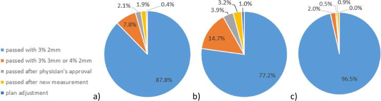
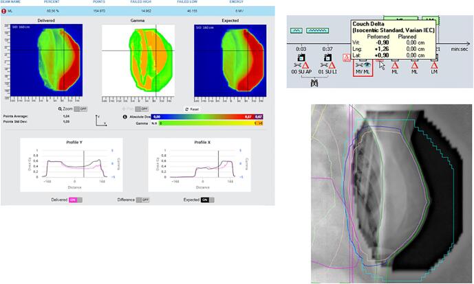
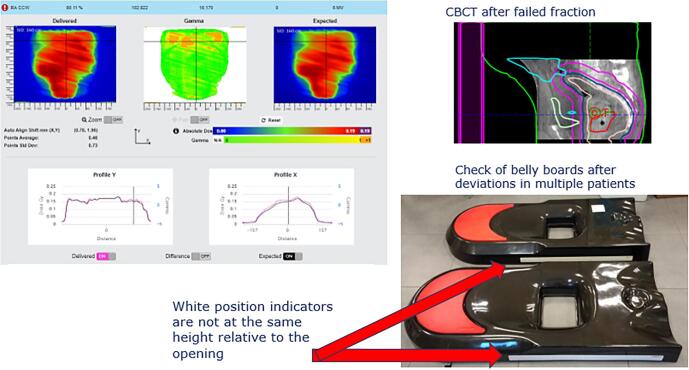
Background and purpose: First reports on clinical use of commercially automated systems for Electronic Portal Imaging Device (EPID)-based dosimetry in radiotherapy showed the capability to detect important changes in patient setup, anatomy and external device position. For this study, results for more than 3000 patients, for both pre-treatment verification and in-vivo transit dosimetry were analyzed.
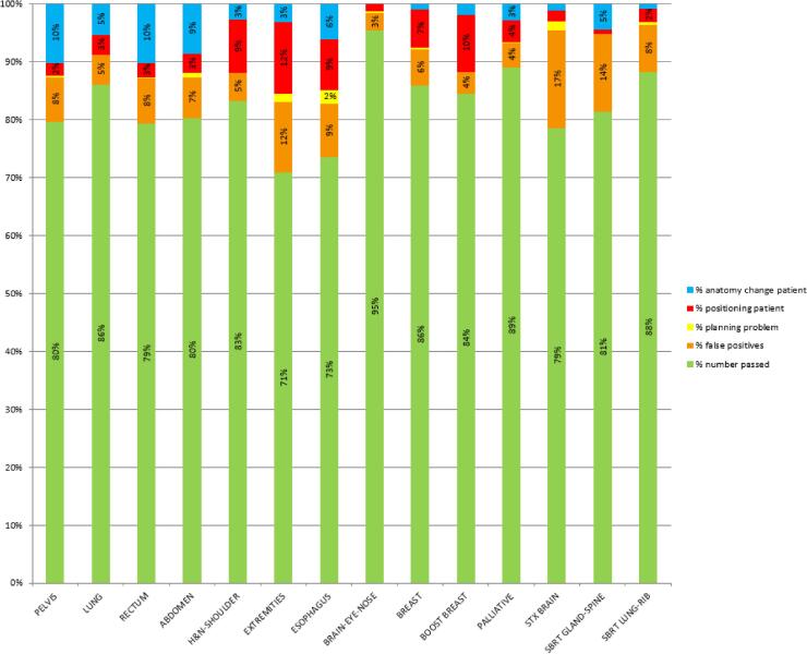
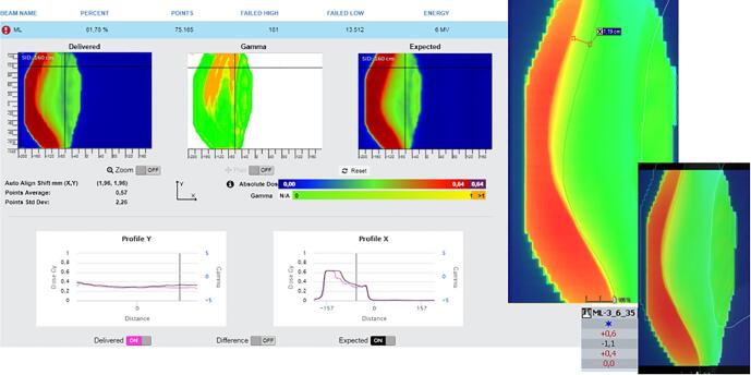
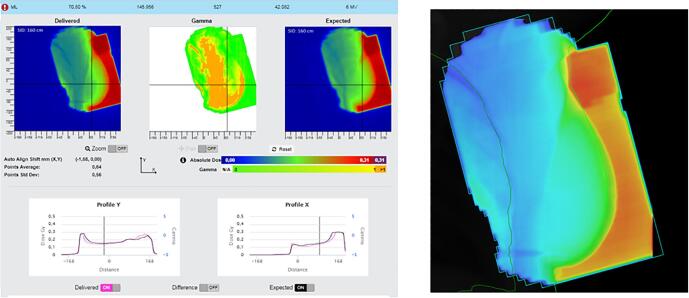
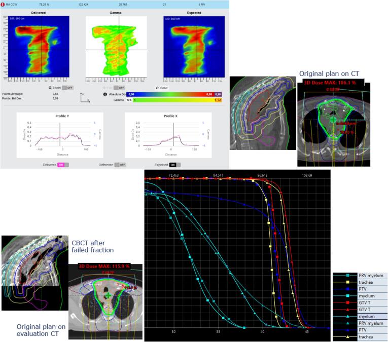
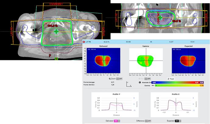
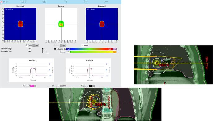
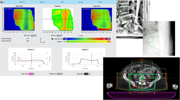
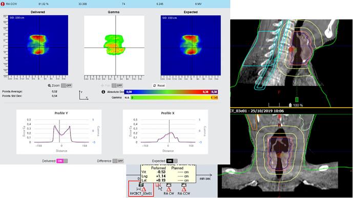
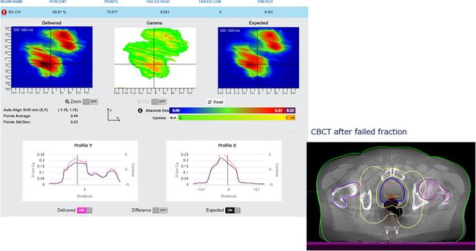
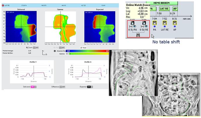
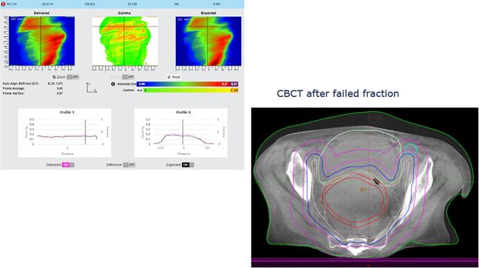
Materials and methods: For all Volumetric Modulated Arc Therapy (VMAT) plans, pre-treatment quality assurance (QA) with EPID images was performed. In-vivo dosimetry using transit EPID images was analyzed, including causes and actions for failed fractions for all patients receiving photon treatment (2018-2019). In total 3136 and 32,632 fractions were analyzed with pre-treatment and transit images respectively. Parameters for gamma analysis were empirically determined, balancing the rate between detection of clinically relevant problems and the number of false positive results.
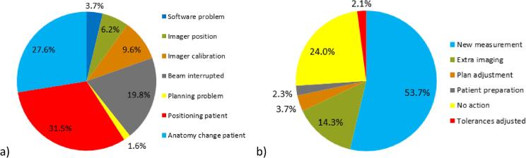
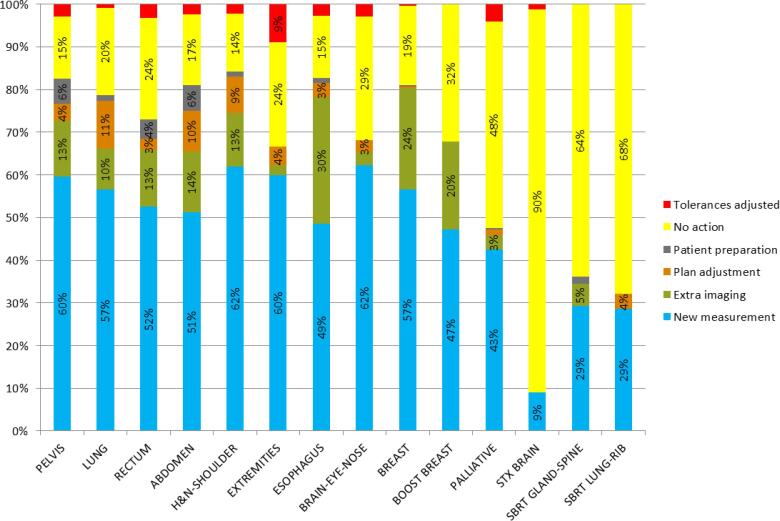
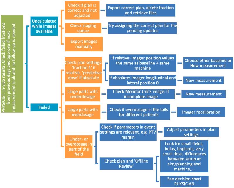
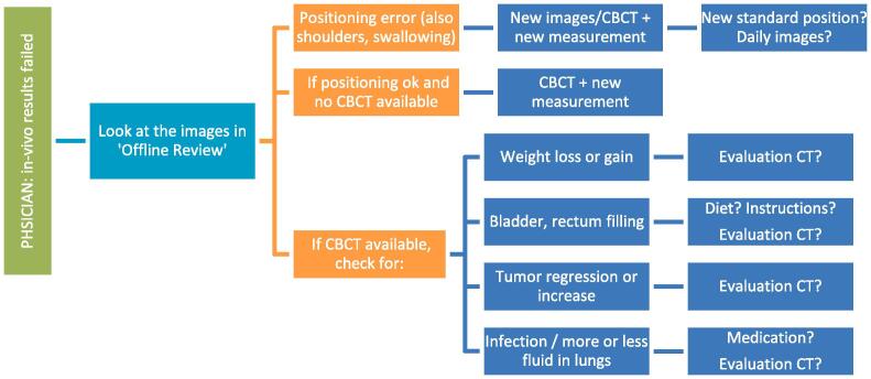
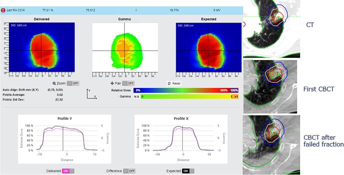
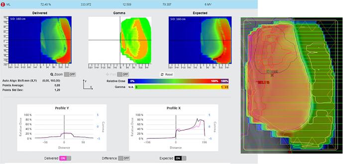
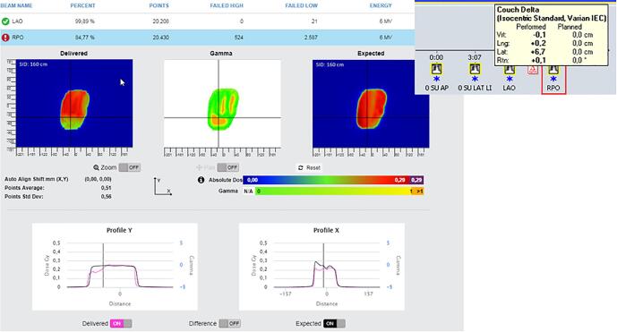
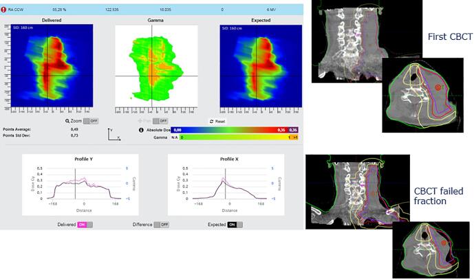
Results: Pre-treatment and in-vivo results depended on machine type. Causes for failed in-vivo analysis included deviations in patient positioning (32%) and anatomy change (28%). In addition, errors in planning, imaging, treatment delivery, simulation, breath hold and with immobilization devices were detected. Actions for failed fractions were mostly to repeat the measurement while taking extra care in positioning (54%) and to intensify imaging procedures (14%). Four percent initiated plan adjustments, showing the potential of the system as a basis for adaptive planning.
Conclusions: EPID-based pre-treatment and in-vivo transit dosimetry using a commercially available automated system efficiently revealed a wide variety of deviations and showed potential to serve as a basis for adaptive planning.
Keywords: In-vivo; Transit dosimetry.
© 2020 The Authors.
Conflict of interest statement
The authors declare the following financial interests/personal relationships which may be considered as potential competing interests: Iridium Kankernetwerk is a member of the SunCHECK Customer Advisory Board and a Reference center for Sun Nuclear Corporation, but there has been no significant financial support for this work that could have influenced its outcome.
Figures
Similar articles
-
A novel approach to SBRT patient quality assurance using EPID-based real-time transit dosimetry : A step to QA with in vivo EPID dosimetry.Strahlenther Onkol. 2020 Feb;196(2):182-192. doi: 10.1007/s00066-019-01549-z. Epub 2020 Jan 10. Strahlenther Onkol. 2020. PMID: 31925465
-
AAPM Task Group Report 307: Use of EPIDs for Patient-Specific IMRT and VMAT QA.Med Phys. 2023 Aug;50(8):e865-e903. doi: 10.1002/mp.16536. Epub 2023 Jun 29. Med Phys. 2023. PMID: 37384416 Free PMC article. Review.
-
Overview of 3-year experience with large-scale electronic portal imaging device-based 3-dimensional transit dosimetry.Pract Radiat Oncol. 2015 Nov-Dec;5(6):e679-87. doi: 10.1016/j.prro.2015.07.001. Epub 2015 Jul 9. Pract Radiat Oncol. 2015. PMID: 26421834
-
The effect of the choice of patient model on the performance of in vivo 3D EPID dosimetry to detect variations in patient position and anatomy.Med Phys. 2020 Jan;47(1):171-180. doi: 10.1002/mp.13893. Epub 2019 Nov 14. Med Phys. 2020. PMID: 31674038
-
A literature review of electronic portal imaging for radiotherapy dosimetry.Radiother Oncol. 2008 Sep;88(3):289-309. doi: 10.1016/j.radonc.2008.07.008. Epub 2008 Aug 14. Radiother Oncol. 2008. PMID: 18706727 Review.
Cited by
-
Assessing the impact of adaptations to the clinical workflow in radiotherapy using transit in vivo dosimetry.Phys Imaging Radiat Oncol. 2023 Jan 30;25:100420. doi: 10.1016/j.phro.2023.100420. eCollection 2023 Jan. Phys Imaging Radiat Oncol. 2023. PMID: 36820237 Free PMC article.
-
Validation of an in vivo transit dosimetry algorithm using Monte Carlo simulations and ionization chamber measurements.J Appl Clin Med Phys. 2024 Feb;25(2):e14187. doi: 10.1002/acm2.14187. Epub 2023 Oct 27. J Appl Clin Med Phys. 2024. PMID: 37890864 Free PMC article.
-
The role of EPID in vivo dosimetry in the risk management of stereotactic lung treatments.Strahlenther Onkol. 2023 Nov;199(11):992-999. doi: 10.1007/s00066-023-02081-x. Epub 2023 May 31. Strahlenther Onkol. 2023. PMID: 37256302
-
Selective de-implementation of routine in vivo dosimetry.J Appl Clin Med Phys. 2023 Jul;24(7):e13953. doi: 10.1002/acm2.13953. Epub 2023 Mar 6. J Appl Clin Med Phys. 2023. PMID: 36877712 Free PMC article. Review.
-
Comparing treatment uncertainty for ultra- vs. standard-hypofractionated breast radiation therapy based on in-vivo dosimetry.Phys Imaging Radiat Oncol. 2022 May 13;22:85-90. doi: 10.1016/j.phro.2022.05.003. eCollection 2022 Apr. Phys Imaging Radiat Oncol. 2022. PMID: 35602547 Free PMC article.
References
-
- Yorke E., Alecu R., Ding L., Fontenla D., Kalend A., Kaurin D. AAPM Radiation Therapy Committee Task Group 62. Medical Physics Publishing; 2005. AAPM report No. 87. Diode in vivo dosimetry for patients receiving external beam radiation therapy.
-
- Ortiz López P., Cosset J.M., Dunscombe P., Holmberg O., Rosenwald J.C., Pinillos Ashton L. ICRP publication 112. A report of preventing accidental exposures from new external beam radiation therapy technologies. Ann ICRP. 2009;39:1–86. - PubMed
-
- International Atomic Energy Agency. Development of procedures for in vivo dosimetry in radiotherapy. Human Health Report No. 8, IAEA, Vienna, 2013. https://www-pub.iaea.org/MTCD/Publications/PDF/Pub1606_web.pdf.
LinkOut - more resources
Full Text Sources
