. 2021 Feb 8;7(2):794-803.
doi: 10.1021/acsbiomaterials.0c01470. Epub 2021 Jan 19.

3D Printed Contact Lenses

Affiliations

3D Printed Contact Lenses

Fahad Alam et al. ACS Biomater Sci Eng. .

Abstract

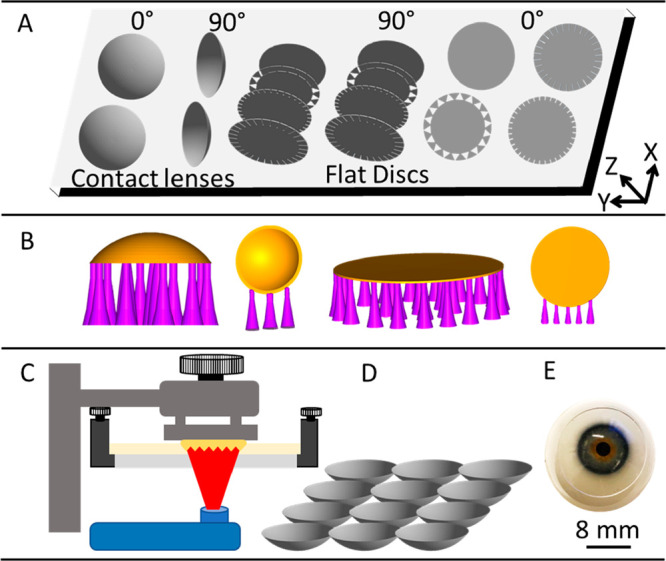
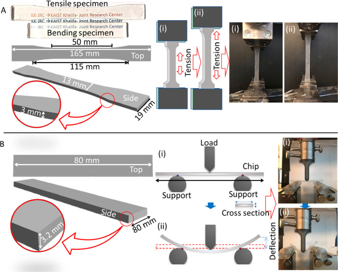
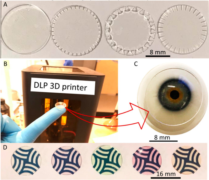
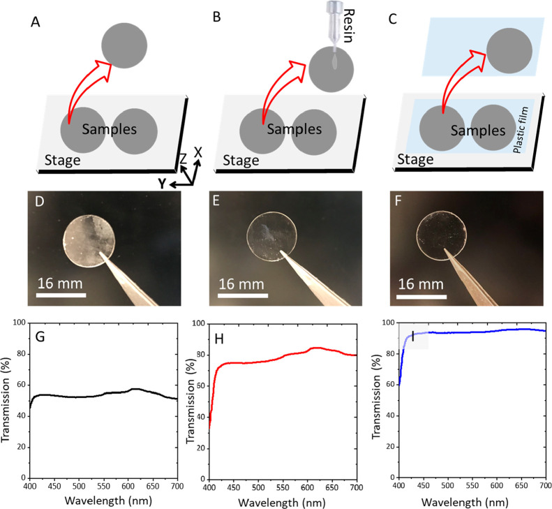
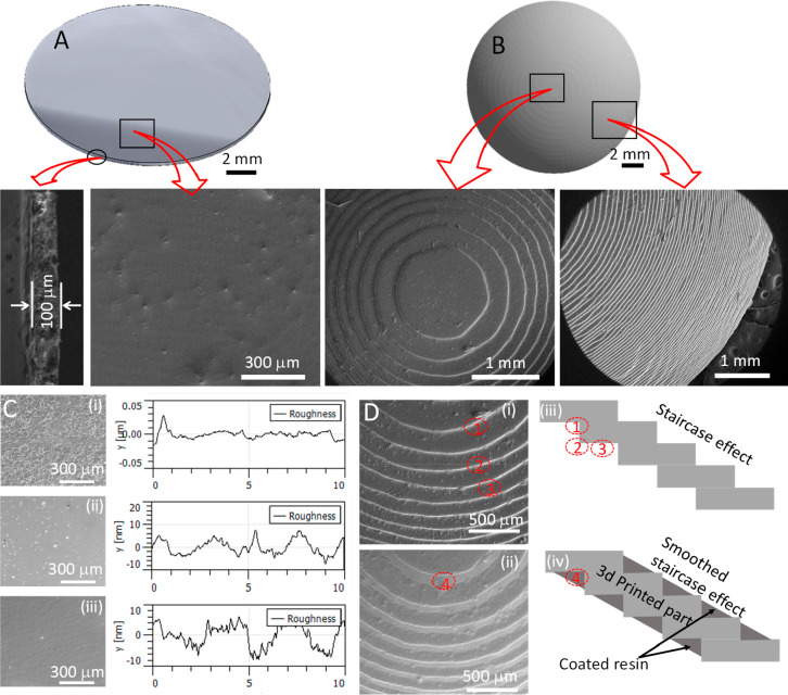
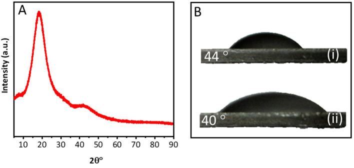
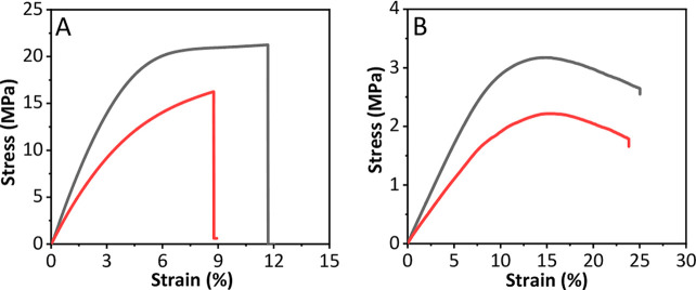
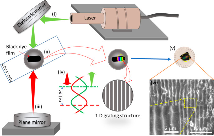
Although the manufacturing processes of contact lenses are well established, the use of additive manufacturing for their fabrication opens many new possibilities to explore. The current study demonstrates the fabrication of personalized smart contract lenses utilizing additive manufacturing. The study includes 3-dimensional (3D) modeling of contact lenses with the assistance of a computer aided designing tool based on standard commercial contact lens dimension, followed by the selection of the suitable materials and 3D printing of contact lenses. The 3D printing parameters were optimized to achieve the desired lens geometries, and a post processing treatment was performed to achieve a smooth surface finish. The study also presents functionalized contact lenses with built-in sensing abilities by utilizing microchannels at the contact lens edges. Tinted contact lenses were printed and nanopatterns were textured onto the contact lens surfaces through holographic laser ablation. 3D printed contact lenses have advantages over conventional contact lenses, offering customized ophthalmic devices and the capability to integrate with optical sensors for diagnostics.

Keywords: additive manufacturing; contact lenses; laser printing; nanopatterning; sensing.


Conflict of interest statement

The authors declare no competing financial interest.

Figures

Figure 1
Figure 1
Schematic representation of the processes involved in DLP 3D printing of contact lenses. (A) Production of the CAD model of the lens, (B) preparation of 3D printer readable files with appropriate supports and two printing orientations, (C) DLP 3D printing, (D) removal and cleaning of the prepared lenses, and (E) end user application of the lenses.
Figure 2
Figure 2
Mechanical testing of the lens material. (A) Samples of tension test and the tensile test setup showing the schematics representation of the dogbone samples and the clamps of the UTM holding the dogbone samples. The samples before and while in tension are shown in the photographs. (B) Three-point bending test of the material. The schematics are showing the test specimen and the process of 3-point bending. The samples before and after bending are shown in photographs as indicated by arrows.
Figure 3
Figure 3
Digital photographs of the lenses and disc fabricated by 3D printing. (A) Flat disc with different integrated microchannel designs. (B) Digital photographs of a curved lens on the tip of a finger. (C) Contact lenses on an eye model showing the transparency of the lens. (D) Digital photographs of the plain and tinted contact (left to right) lenses showing the feasibility of the manufacturing process and the optical visibility.
Figure 4
Figure 4
Three stages of optimization of the samples while printing. (A) Printing directly on the print bed without post processing. (B) Printing on print bed, followed by resin coating, and (c) printing on a PVC thin film attached on the print bed. Photographs of the samples obtained via (D) the print bed, (E) resin coating and (F) from the PVC film. Similarly, the transmittance spectra with respect to wavelength are shown for samples (G) obtained directly from print bed, (H) resin-coated sample, and (I) obtained from PVC film.
Figure 5
Figure 5
Different developmental stages in optimization of lens and discs with adequate transmittance required for a contact lens. (A) SEM micrograph of the flat disc, the top surface and cross section are highlighted with the red arrows. (B) SEM micrograph of the contact lens, the top surface and side wall of the lens are highlighted with the red arrows. (C) SEM micrograph of the flat disc manufactured with 3D printing showing the improvement in the surface roughness by opting the 3 different approach (i) directly print on print bed, (ii) post-print resin-coated, and (iii) printed on PVC plastic film. The corresponding surface topography obtained from AFM are shown in the right side. (D) SEM micrographs of the contact lens before (i) and after (ii) dip coating after 3D printing and the effect of dip coating is depicted with the help of schematics (iii and iv).
Figure 6
Figure 6
Material propertied of the lens material. (A) XRD spectra and (B) surface wettability: (i) 5 μL droplet and (ii) 15 μL water droplet.
Figure 7
Figure 7
(A) Stress–strain curve obtained after tension test and (B) stress–strain cure obtained after 3-point bending test.
Figure 8
Figure 8
Fabrication of the nanopattern on the surface of contact lens using a DLIP in Denisyuk reflection mode. Nd:YAG laser beam (1064 nm focused beam) was used to create the nanopattern on the surface of the lens. (i) The laser beam was guided by a mirror and (ii) passed through the dyed contact lens. (iii) The laser was reflected back from a plane mirror placed perpendicular to the incident beam. (iv) The ablation process created a 1D grating structure, which displayed a rainbow holographic effect due to diffraction. (v) The digital photograph of the hologram is shown on the contact lens manufactured via 3D printing. (vi) The SEM micrographs show the nanopattern.
Figure 9
Figure 9
Optical polarization spectroscopy of the dyed contact lenses manufactured via 3D printing. (A) Schematic representation of the setup used for the measurement of the polarization spectra. The transmission of polarized and unpolarized light with respect to wavelength was recorded at various polarization angle. The plots are shown along with their corresponding digital images of the dyed contact lenses: (B) no color, (C) blue, (D) green, (E) red, and (F) yellow color.

References

    1. Villena Gonzales W.; Mobashsher A. T.; Abbosh A. The Progress of Glucose Monitoring—A Review of Invasive to Minimally and Non-Invasive Techniques, Devices and Sensors. Sensors 2019, 19 (4), 800.10.3390/s19040800. - DOI - PMC - PubMed
    1. Liu Y.; Pharr M.; Salvatore G. A. Lab-On-Skin: A Review of Flexible and Stretchable Electronics for Wearable Health Monitoring. ACS Nano 2017, 11 (10), 9614–9635. 10.1021/acsnano.7b04898. - DOI - PubMed
    1. Bariya M.; Shahpar Z.; Park H.; Sun J.; Jung Y.; Gao W.; Nyein H. Y. Y.; Liaw T. S.; Tai L.-C.; Ngo Q. P.; et al. Roll-To-Roll Gravure Printed Electrochemical Sensors for Wearable and Medical Devices. ACS Nano 2018, 12 (7), 6978–6987. 10.1021/acsnano.8b02505. - DOI - PubMed
    1. Ha M.; Lim S.; Ko H. Wearable and Flexible Sensors for User-Interactive Health-Monitoring Devices. J. Mater. Chem. B 2018, 6 (24), 4043–4064. 10.1039/C8TB01063C. - DOI - PubMed
    1. Wang X.; Liu Z.; Zhang T. Flexible Sensing Electronics for Wearable/Attachable Health Monitoring. Small 2017, 13 (25), 1602790.10.1002/smll.201602790. - DOI - PubMed

Publication types