. 2021 Jan 19;12(1):455.
doi: 10.1038/s41467-020-20708-w.

A self-matched leaky-wave antenna for ultrahigh-field magnetic resonance imaging with low specific absorption rate

Affiliations

A self-matched leaky-wave antenna for ultrahigh-field magnetic resonance imaging with low specific absorption rate

G Solomakha et al. Nat Commun. .

Abstract

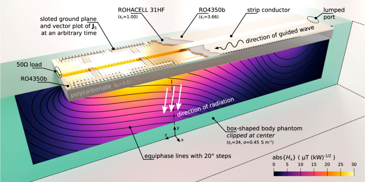
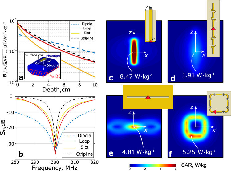
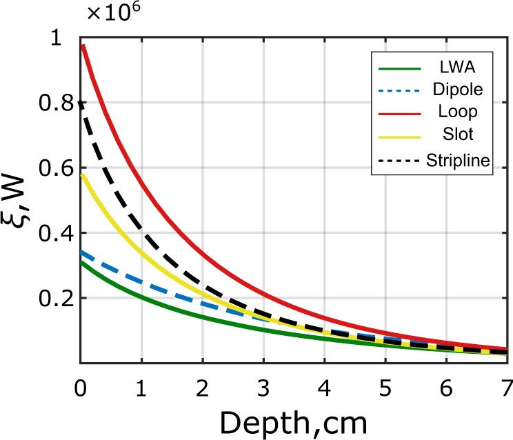
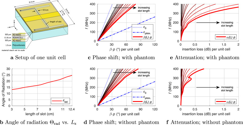
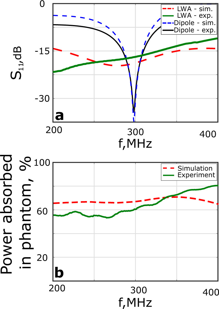
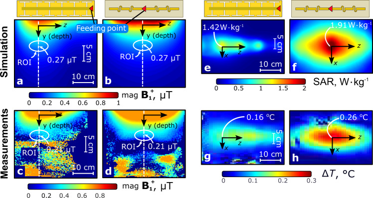
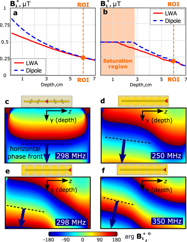
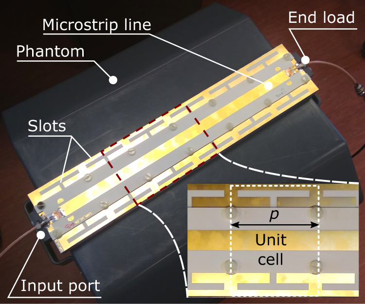
The technology of magnetic resonance imaging is developing towards higher magnetic fields to improve resolution and contrast. However, whole-body imaging at 7 T or even higher flux densities remains challenging due to wave interference, tissue inhomogeneities, and high RF power deposition. Nowadays, proper RF excitation of a human body in prostate and cardiac MRI is only possible to achieve by using phased arrays of antennas attached to the body (so-called surface coils). Due to safety concerns, the design of such coils aims at minimization of the local specific absorption rate (SAR), keeping the highest possible RF signal in the region of interest. Most previously demonstrated approaches were based on resonant structures such as e.g. dipoles, capacitively-loaded loops, TEM-line sections. In this study, we show that there is a better compromise between the transmit signal [Formula: see text] and the local SAR using non-resonant surface coils generating a low electric field in the proximity of their conductors. With this aim, we propose and experimentally demonstrate a leaky-wave antenna implemented as a periodically-slotted microstrip transmission line. Due to its non-resonant radiation, it induces only slightly over half the peak local SAR compared to a state-of-the-art dipole antenna but has the same transmit efficiency in prostate imaging at 7 T. Unlike other antennas for MRI, the leaky-wave antenna does not require to be tuned and matched when placed on a body, which makes it easy-to-use in prostate imaging at 7 T MRI.


Conflict of interest statement

The authors declare no competing interests.

Figures

Fig. 1
Fig. 1. Proposed RF excitation mechanism through non-resonant radiation of leaky waves.
The exciting slotted microstrip line radiates into a box-shaped human body phantom for body MRI RF excitation. The color plot shows the normalized magnitude of the simulated Hx distribution, while black contours represent wavefronts in the conductive medium. Calculated surface current density distribution on the slotted ground plane is shown with black arrows.
Fig. 2
Fig. 2. Correspondence between the peak local SAR and resonant properties of surface coils for body imaging at 7 T.
a B1+/SAR factor for different depths of ROI; b reflection coefficient at the input of a coil; simulated local SAR patterns at 1 W of accepted transmit power at the top surface of the phantom: c stripline; d fractionated dipole; e slot and f loop coil.
Fig. 3
Fig. 3. Comparison of different MRI coil types according to their reactive near fields.
Figure of merit based on the difference between electric and magnetic energy density as defined in equation (1) for different coil types equally fed with 1 W of accepted power as a function of depth in the phantom.
Fig. 4
Fig. 4. A parametric numerical investigation of dispersion characteristics based on single unit cell.
Geometry of the unit cell (a), angle θrad of the leaky-wave radiation for the loaded transmission line (b), phase shift (β·p) and insertion loss (dB) (αp20log(10)1) in the microstrip leaky-wave transmission line per unit cell (c, df). The length of the slot is varied from 3 cm to 12.4 cm. In cases c, e, the transmission line is placed on a phantom while cases d, f represent the free space environment of the transmission line. The bold curves are for the LWA with an optimal length of 12.4 cm.
Fig. 5
Fig. 5. Simulated and measured properties of the optimized LWA and the reference dipole antenna.
a S11 at the feed port and b relative power ν radiated into and absorbed by the phantom.
Fig. 6
Fig. 6. Simulated and measured field distributions for 1 W of accepted input transmit power in the octagonal phantom.
B1+ in the YZ-plane of the phantom for the LWA (a, c) and fractionated dipole antenna (b, d); local SAR and ΔT in the top plane (XZ) for LWA (e, g) and dipole antenna (f, h). The feeding point of the antennas is indicated with a red triangle.
Fig. 7
Fig. 7. Numerical and experimental B1+ magnitude and phase profiles.
Simulated (a) and measured (b) B1+ vs. depth profiles for the LWA and fractionated dipole antenna element in the phantom (profiles were plotted along the corresponding dashed lines shown in Fig. 6a–d); simulated phase patterns for B1+ in the phantom for the dipole antenna at 298 MHz (c), and for the LWA at 250 MHz (d), 298 MHz (e) and 350 MHz (f). The tangent to the phase front for each phase pattern is indicated with a black dashed line.
Fig. 8
Fig. 8. Constructed protype of leaky-wave antenna.
Photograps of the fabricated prototype of the optimized LWA placed over a pelvis-shaped homogeneous phantom for MRI characterization.
Fig. 9
Fig. 9. In-vivo and safety characterization of four-element LWA array.
Simulated B1+ for the four-element LWA array configuration (a) and a fractionated dipole array (b) in the transverse slice through the prostate of the human body Duke anatomical model for 1 W of accepted power. The corresponding SAR for the LWA array (c) and fractionated dipole array (d) in a the transverse slice through the maximum of local SAR. In-vivo B1+ map in healthy volunteer for LWA array (e) and the dipole array (f). g In-vivo T1-weighted MR image (transverse slice through the prostate) of a healthy volunteer obtained using a four-element array of LWAs and h of dipoles.

References

    1. Ladd ME, et al. Pros and cons of ultra-high-field mri/mrs for human application. Prog. Nucl. Magn. Reson. Spectrosc. 2018;109:1–50. doi: 10.1016/j.pnmrs.2018.06.001. - DOI - PubMed
    1. Trattnig S, et al. Key clinical benefits of neuroimaging at 7T. NeuroImage. 2018;168:477 – 489. doi: 10.1016/j.neuroimage.2016.11.031. - DOI - PMC - PubMed
    1. Barry RL, Vannesjo SJ, By S, Gore JC, Smith SA. Spinal cord mri at 7 t. NeuroImage. 2018;168:437 – 451. doi: 10.1016/j.neuroimage.2017.07.003. - DOI - PMC - PubMed
    1. Morris LS, et al. Ultra-high field MRI reveals mood-related circuit disturbances in depression: a comparison between 3-Tesla and 7-Tesla. Transl. Psychiatry. 2019;9:94. doi: 10.1038/s41398-019-0425-6. - DOI - PMC - PubMed
    1. Webb AG, Collins CM. Parallel transmit and receive technology in high-field magnetic resonance neuroimaging. Int. J. Imaging Syst. Technol. 2010;20:2–13. doi: 10.1002/ima.20219. - DOI

Publication types

MeSH terms