. 2019 May;28(5):055006.
doi: 10.1088/1361-665X/ab0ea2. Epub 2019 Apr 1.

Elastic Shape Morphing of Ultralight Structures by Programmable Assembly

Affiliations

Elastic Shape Morphing of Ultralight Structures by Programmable Assembly

Nicholas B Cramer et al. Smart Mater Struct. 2019 May.

Abstract

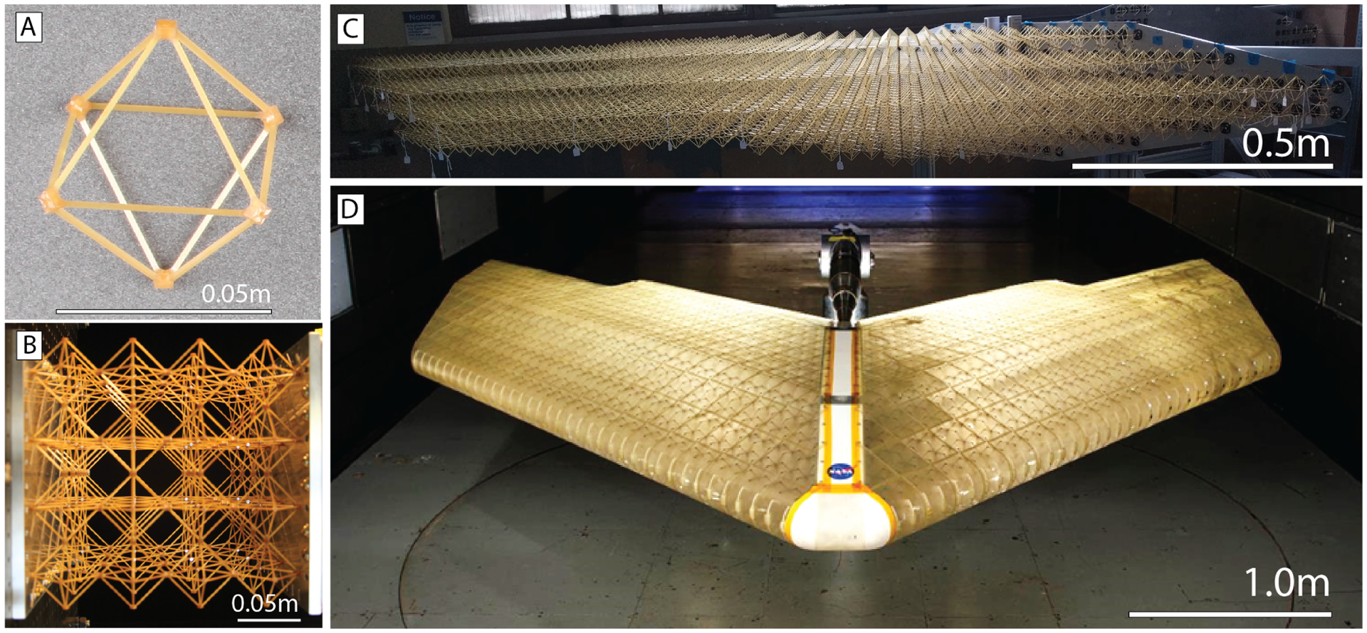
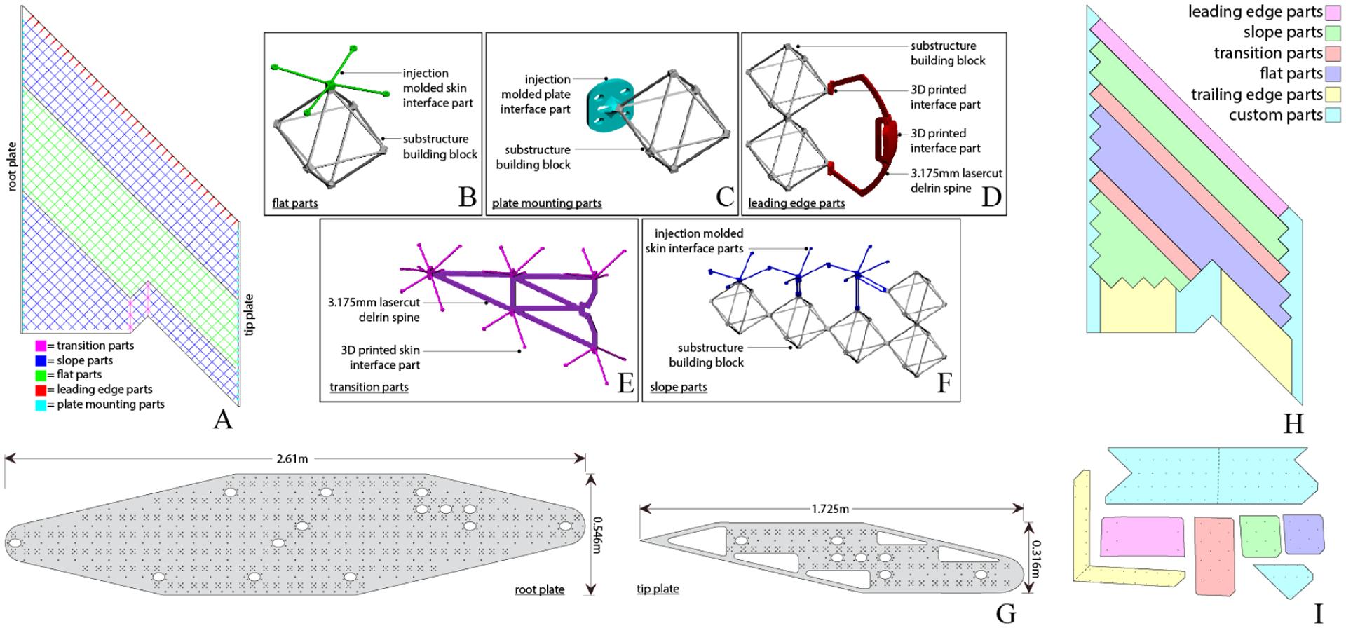
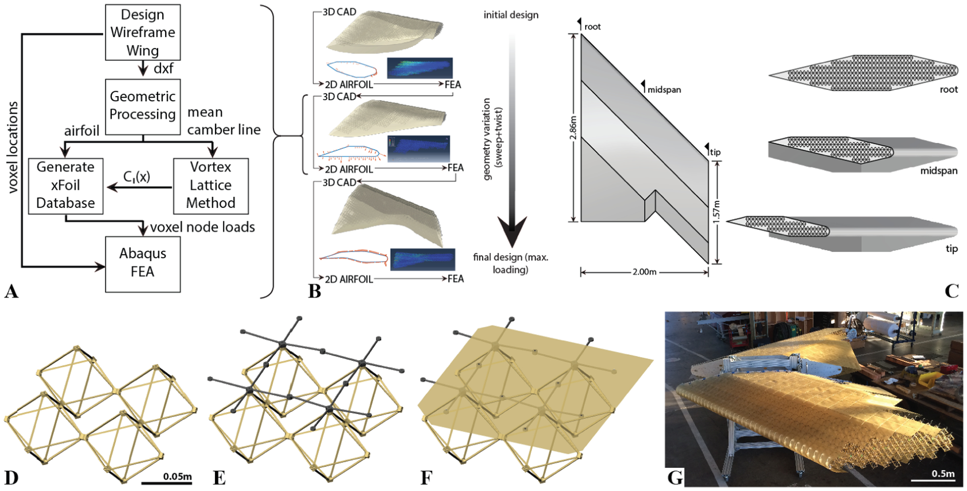
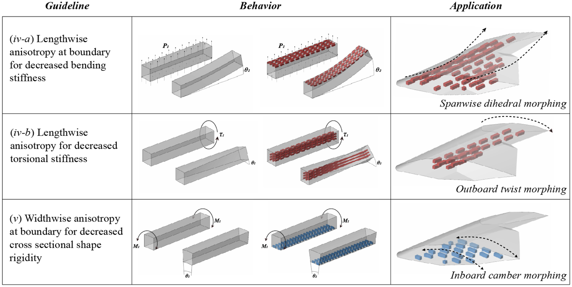
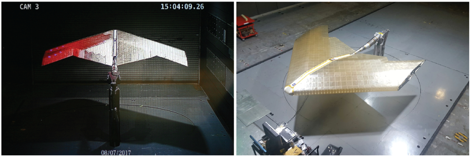
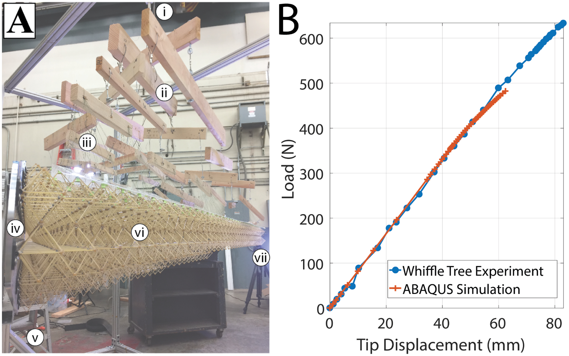
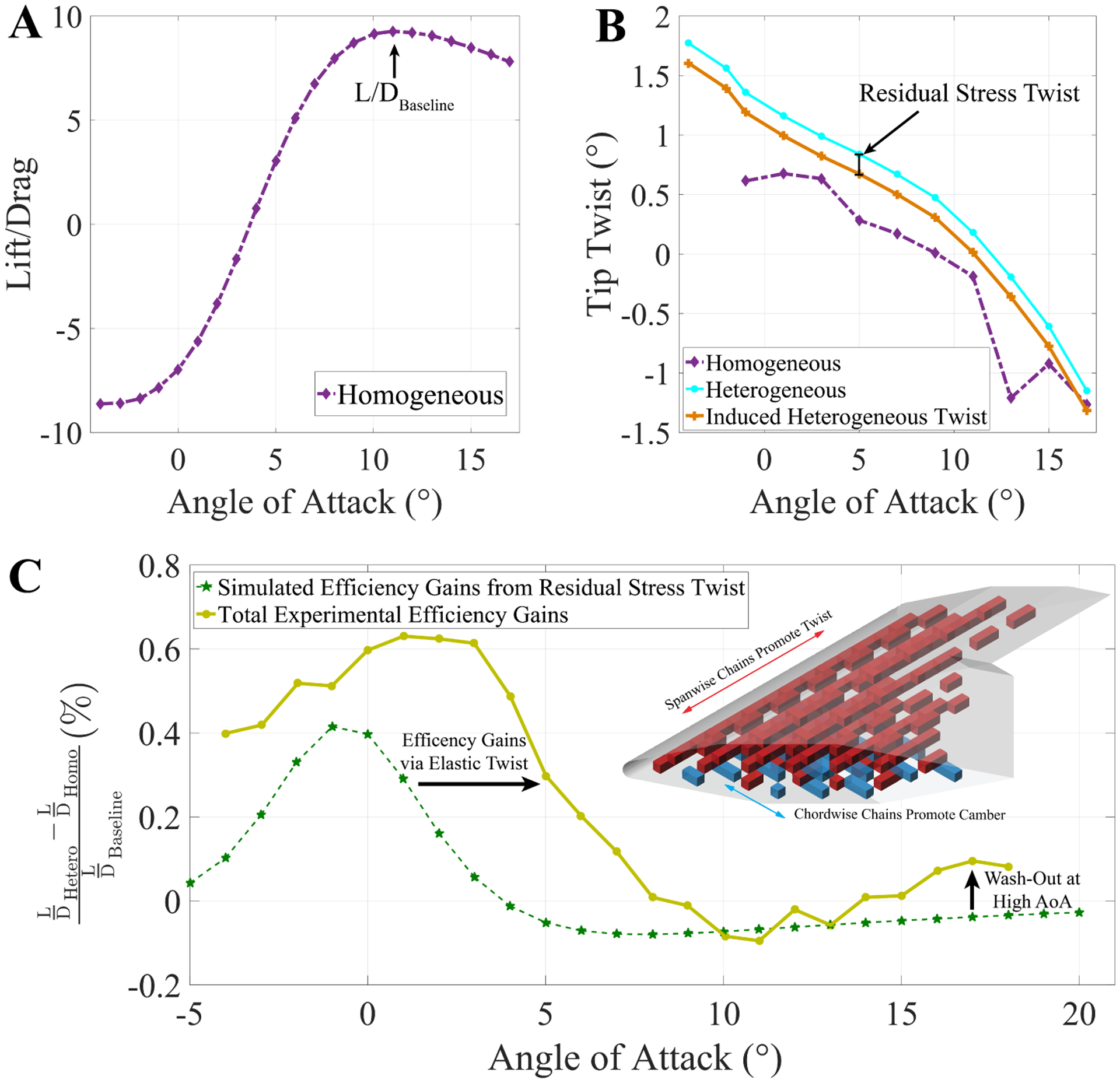
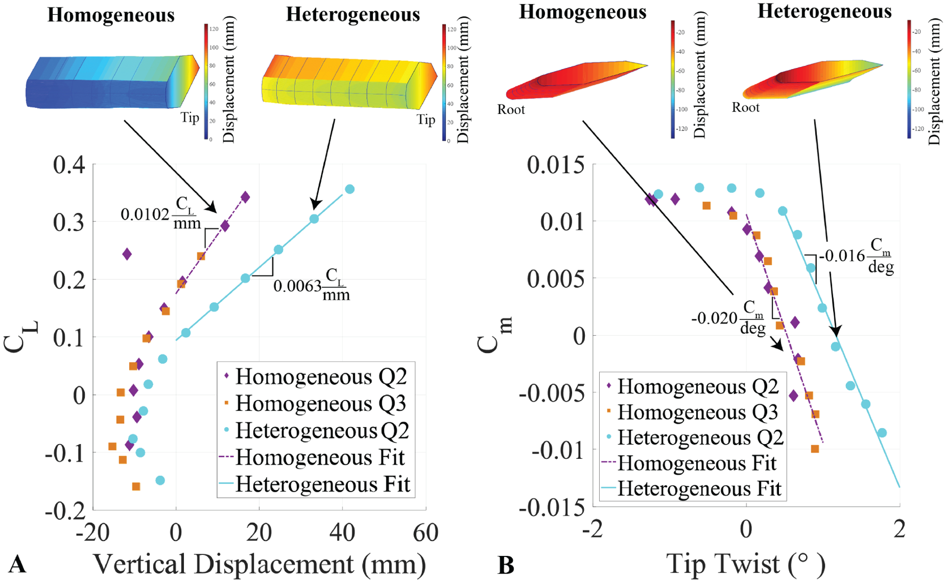
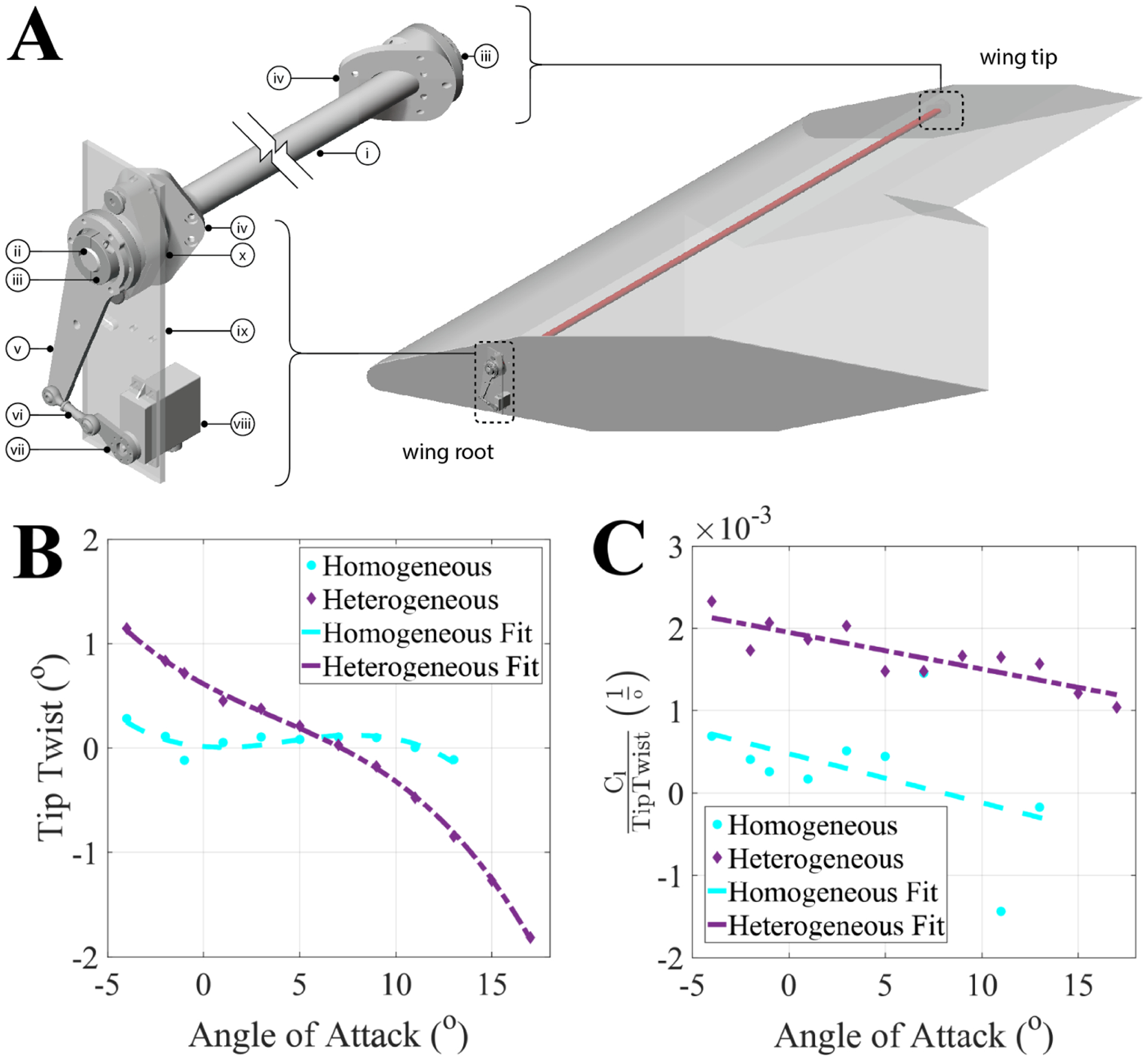
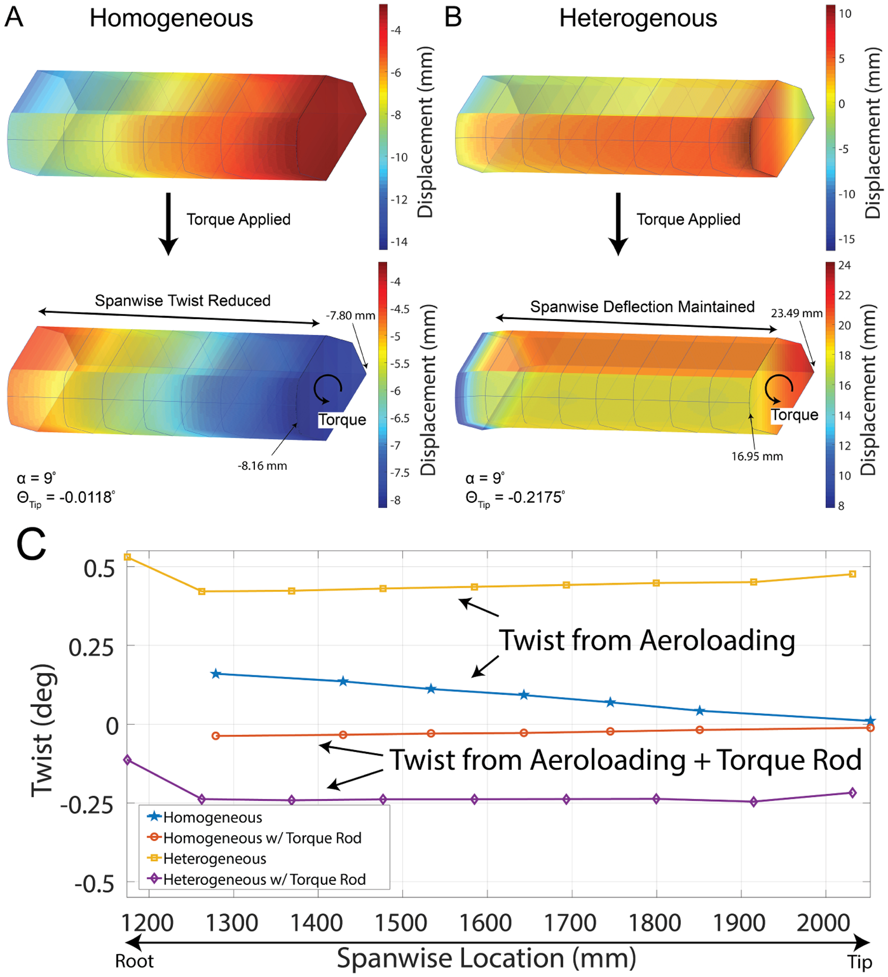
Ultralight materials present an opportunity to dramatically increase the efficiency of load-bearing aerostructures. To date, however, these ultralight materials have generally been confined to the laboratory bench-top, due to dimensional constraints of the manufacturing processes. We show a programmable material system applied as a large-scale, ultralight, and conformable aeroelastic structure. The use of a modular, lattice-based, ultralight material results in stiffness typical of an elastomer (2.6 MPa) at a mass density typical of an aerogel (5.6 m g c m 3 ). This, combined with a building block based manufacturing and configuration strategy, enables the rapid realization of new adaptive structures and mechanisms. The heterogeneous design with programmable anisotropy allows for enhanced elastic and global shape deformation in response to external loading, making it useful for tuned fluid-structure interaction. We demonstrate an example application experiment using two building block types for the primary structure of a 4.27m wingspan aircraft, where we spatially program elastic shape morphing to increase aerodynamic efficiency and improve roll control authority, demonstrated with full-scale wind tunnel testing.


Figures

Figure 1:
Figure 1:
A large-scale, ultralight adaptive structural system. A) Modular building block unit, B) 4×4×4 unit cube during mechanical testing, C) Single half-span wing structure composed of 2088 building block units, D) Blended wing body aerostructure with skin, mounted to central load balance in the 14×22 subsonic wind tunnel at NASA Langley Research Center
Figure 2:
Figure 2:
Interface building blocks and plates. A) Top view with color code indicating location and types of interface parts, B–F) Interface parts and descriptions, G) Root and tip plate, H) Top view with color coded skin panel types, I) Sample parts unrolled as flat surfaces ready for cutting.
Figure 3:
Figure 3:
Building block toolkit design work-flow for ultralight aerostructures. A) 2D airfoil section design, 3D lattice material aerostructure, and FEA with aerodynamic loading and elastic deformation. B) The iterative process utilizing software work-flow to arrive at the final design, C) Final Design, D) Substructure building blocks, E) Interface building blocks, F) Skin building block, G) Large scale ultralight aerostructure near completion of manufacturing.
Figure 4:
Figure 4:
Guidelines, behaviors, and applications of anisotropic spatial programming.
Figure 5:
Figure 5:
Views of wind tunnel setup. (L) Rear view, (R) Front/side view.
Figure 6:
Figure 6:
ABAQUS simulations of various possible anisotropic wing designs using the same building blocks, demonstrating the ability to tune the primary performance metrics through different building block material types and no geometry changes. A) shows through the reduction in the leading edge stiffness the wing would have its tip twist upward under a uniform load, resulting in ”wash in,” which at low angles of attack can result in increased aircraft efficiency. B) shows that through balancing the leading edge and trailing edge stiffness the same deflection of A) can be achieved with no twist, C) is the opposite design to A) which results in ”wash out” which is desirable for enhanced stability and high angle of attack maneuvers.
Figure 7:
Figure 7:
Substructure static load test and simulation. A) the whiffletree test configuration, labeled are the following: i) single point load, ii) whiffle tree load distribution system, iii) cable system for tree to structure load distribution, iv) wing root base plate mounted to test stand, v) fixture weight, vi) building block structure under test load, vii) tip displacement measurement. B) comparison between the whiffletree test and the ABAQUS simulations, showing effecting FEA prediction of structural response behavior.
Figure 8:
Figure 8:
The lift to drag ratio for the baseline homogeneous wing is shown. A) Lift-Drag curve of the homogeneous design and highlighting the defined baseline operation value. B) compares the twist between the baseline homogeneous and programmed heterogeneous models as well as the estimated tip twist of the programmed heterogeneous model due to the change in stiffness. C) compares the total efficiency gains to the gains through the initial residual stress induced shape change, as well as the tuned changes in stiffness due to the programmed heterogeneous building block placement, shown in the right-hand corner of Figure C.
Figure 9:
Figure 9:
Quasi-static aeroelastic stiffness. A) shows the normalized loading curve of vertical lift displacement and B) shows the normalized pitching moment curve of tip twist, this is the representation of the aeroelastic stiffness of the structure where the stiffness coefficients that are being tuned are the slopes of the linear region.
Figure 10:
Figure 10:
Actuation System and Results. A) A 31.75mm OD, 25.4mm ID carbon fiber tube (i) transfers torque to the wing tip from the actuation source at the root. A 25.4mm OD keyed aluminum shaft (ii) is epoxied to the end of the tube, with 25.4mm extending and clamped by a keyed shaft collar (iii). At the tip, this shaft collar bolts to a milled aluminum fixture (iv) which bolts to the carbon fiber tip plate (not shown). At the root, the shaft collar bolts to a 6mm thick aluminum plate armature (v). This armature connects to a ball-bearing linkage (vi), which connects to a 6mm thick aluminum servo horn armature (vii). This bolts to a high torque servo (viii), which is fixtured to a 6mm aluminum mounting plate (ix). This plate is bolted to a mounted bearing with flanges (x) which bolts to a milled aluminum fixture (iv), which bolts to the root plate on either side. B) shows the tip twist of the aerostructure with the torque rod engaged. The structural tunning allowed for a large amount of tip twist over the range of angles of attack even with the addition of the torque rod. The effect of the increase in flexibility can be seen in C) where the roll authority per tip twist degree was increased for the baseline homogeneous model.
Figure 11:
Figure 11:
Shape effects of torque rod and heterogeneous configurations. A) and B) show the displacement of the homogeneous and heterogeneous configurations with the impact of the torque rod. C) compares the span-wise twist of each of the configurations and demonstrates that the heterogeneous design results in the nearly flat distribution of twist through the outboard span.

References

    1. Jun JW, Silverio M, Llubia JA, Markopoulou A, Dubor A et al. 2017
    1. Senatore G, Duffour P and Winslow P 2018. Engineering Structures 167 608–628
    1. Joshi S, Tidwell Z, Crossley W and Ramakrishnan S 2004. Comparison of morphing wing stategies based upon aircraft performance impacts 45th AIAA/ASME/ASCE/AHS/ASC Structures, Structural Dynamics & Materials Conference p 1722
    1. Barbarino S, Bilgen O, Ajaj RM, Friswell MI and Inman DJ 2011. Journal of intelligent material systems and structures 22 823–877
    1. Weisshaar TA. Morphing aircraft technology-new shapes for aircraft design Tech. rep. PURDUE UNIV LAFAYETTE IN. 2006.

LinkOut - more resources