

Interaction of delaminations and matrix cracks in a CFRP plate, Part II: Simulation using an enriched shell finite element model
- PMID: 33479561
- PMCID: PMC7816820
- DOI: 10.1016/j.compositesa.2017.10.006
Interaction of delaminations and matrix cracks in a CFRP plate, Part II: Simulation using an enriched shell finite element model
Abstract
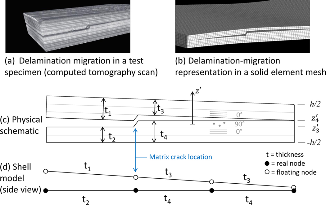
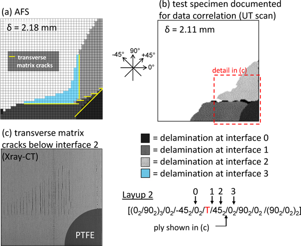
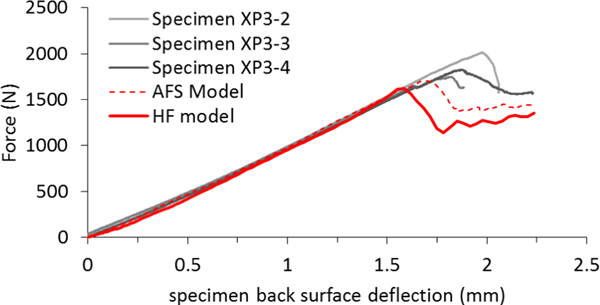
Numerical simulations are presented of a recently developed test which creates multiple delaminations in a CFRP laminate specimen that grow and interact via transverse matrix cracks [1]. A novel shell element enriched with the Floating Node Method, and a damage algorithm based on the Virtual Crack Closure Technique, were used to successfully simulate the tests. Additionally, a 3D high mesh fidelity model based on cohesive zones and continuum damage mechanics was used to simulate the tests and act as a representative of other similar state-of-the-art high mesh fidelity modeling techniques to compare to the enriched shell element. The enriched shell and high mesh fidelity models had similar levels of accuracy and generally matched the experimental data. With runtimes of 36 minutes for the shell model and 55 hours for the high mesh fidelity model, the shell model is 92 times faster than the high-fidelity simulation.
Keywords: A. Laminates; B. Delamination; B. Fracture; C. Finite element analysis (FEA).
Figures


References
-
- Hinton M, Kaddour A, Soden P, The world-wide failure exercise: Its origin, concept and content, in: Failure criteria in fiber reinforced polymer composites: the world wide failure exercise, Elsevier, Amsterdam, 2004, pp. 2–28.
-
- Kaddour A, Hinton M, Smith P, Li S, The background to the third world-wide failure exercise, Journal of Composite Materials 47 (20–21) (2013) 2417–2426.
-
- Rose C, Dávila C, Leone F, Analysis methods for progressive damage of composite structures, NASA/TM 2013–218024, NASA, 2013.
-
- Allison J, Integrated computational materials engineering: A perspective on progress and future steps, JOM: The Journal of the Minerals, Metals and Materials Society 63 (4) (2011) 15.
Grants and funding
LinkOut - more resources
Full Text Sources