. 2021 Jan 20;14(3):490.
doi: 10.3390/ma14030490.

Directional Water Wicking on a Metal Surface Patterned by Microchannels

Affiliations

Directional Water Wicking on a Metal Surface Patterned by Microchannels

Nima Abbaspour et al. Materials (Basel). .

Abstract

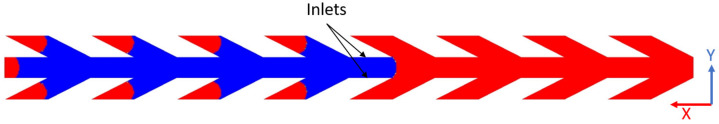
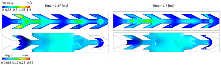
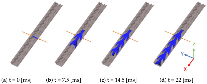
This work focuses on the simulation and experimental study of directional wicking of water on a surface structured by open microchannels. Stainless steel was chosen as the material for the structure motivated by industrial applications as fuel cells. Inspired by nature and literature, we designed a fin type structure. Using Selective Laser Melting (SLM) the fin type structure was manufactured additively with a resolution down to about 30 μm. The geometry was manufactured with three different scalings and both the experiments and the simulation show that the efficiency of the water transport depends on dimensionless numbers such as Reynolds and Capillary numbers. Full 3D numerical simulations of the multiphase Navier-Stokes equations using Volume of Fluid (VOF) and Lattice-Boltzmann (LBM) methods reproduce qualitatively the experimental results and provide new insight into the details of dynamics at small space and time scales. The influence of the static contact angle on the directional wicking was also studied. The simulation enabled estimation of the contact angle threshold beyond which transport vanishes in addition to the optimal contact angle for transport.

Keywords: Lattice Boltzmann Method; Selective Laser Melting Manufacturing; Volume of Fluid; capillarity, 3D simulation; directional wicking; microstructure; patterned surface; wetting dynamics.


Conflict of interest statement

The authors declare no conflict of interest.

Figures

Figure 1
Figure 1
Fin shaped structures added to a flat surface. Top views of the fin-shaped structure studied here and manufactured by Selective Laser Melting (SLM) in a picture from above (left), CAD in an isometric view (middle), and original Polydimethylsiloxane (PDMS) part (right). Notice the different scales and compare the rough metallic structure manufactured by SLM (left) with the smooth surface considered in [16] made of resin (right).
Figure 2
Figure 2
Three adjacent structures exhibiting fin shaped channels added to the steel base by SLM. (left) Actual A, B and C structures. (right) CAD design documenting the total length and width of each structure, in millimeters.
Figure 3
Figure 3
The pictures represent the basic element of structure manufactured by SLM. (left) Structure A and (right) structure C of the experimental set-up (Figure 2) corresponding to the smallest and largest lengths specified in Figure 4. Colours indicate height measured from the steel platform.
Figure 4
Figure 4
A single cell of the pattern from which is deduced the capillaries. The blue colored part is the fused melted metal with a height of 0.1 mm. The bottom of the capillary colored white. Both parts create an elementary cell which is included in the rectangle ‘abcd’. Adding copies of this rectangle adjacent to its parallel to y sides defines one channel and its walls. Then, adding adjacent copies of the ensemble forms the capillaries for structure A, B or C.
Figure 5
Figure 5
Time evolution of directional drop wicking on structure B. The bottom of the channel appears as white and the top of the structure is dark. Water is colored for better visibility. The first picture at time t0 present the pipette that places a water drop on B structure. At time t1 the drop has begun to wick through the channels. At time t2, the structure is completely flooded in the positive direction while wicking progress is slower in the negative direction. Finally at time t3 transport in the negative direction is completed.
Figure 6
Figure 6
Average velocity absolute values of water wicking in x and −x directions for the three different channels A, B and C.
Figure 7
Figure 7
Evolution of water transport in channel type B in the negative direction. Experimental conditions are the same as in Figure 5. Water is colored in blue for better visibility and the triple line is highlighted by a bold blue line. Both red arrows for the panel at t=0 [ms] indicates the presence of water in the tip of the fin.
Figure 8
Figure 8
Evolution of water transport in channel type A in the positive direction. Experimental conditions are the same as in Figure 5. Many chemical defects slow down the dynamics. Water is delimited by a blue line for better visibility. Red dots of the snapshot at t=9.2 [ms] highlight the acute edges discussed in the text.
Figure 9
Figure 9
VOF two-dimensional simulation with θ=50 and the geometry of the horizontal section of channel A.
Figure 10
Figure 10
Snapshots of the asymmetric transport using the 2D VOF simulation. Parameters as in Figure 9.
Figure 11
Figure 11
3D simulation of liquid wicking driven by capillary forces on channel A. Blue color represents liquid volume. Contact angle is 50°. The simulation domain is eight elementary cells long. The parallelepiped size is x=0.7 mm, y=0.38 mm, and z=0.4 mm.
Figure 12
Figure 12
Simulated liquid velocity and free surface height during the wicking of a parallelepiped of liquid over a single fin shaped channel. For each sub-figure, the color scale displays the norm of the velocity field in the upper panel and the liquid height distribution for the bottom panel. Contact angle is 50°. The simulation domain consists of 6 elementary cells. The initial liquid parallelepiped is one elementary cell long. Figure credit from [37] Figure 4.
Figure 13
Figure 13
VOF simulation detailing fin filling in the x direction. The continuous color represents the liquid free surface. Arrows display the velocity on the liquid free surface with a color code for the amplitude. However, instead of being started from an initial condition as for Figure 11 and Figure 12, the simulation is issued from the continuous fluid inlet condition described in Section 5.4. The time is set to zero when the liquid enters the V region.
Figure 14
Figure 14
Average velocity of the front as a function of the static contact angle θ. Blue crosses indicate front velocity in the +x direction while red dots indicate the front velocity −x. Beyond θ30 the front in the −x direction is pinned and then velocity is not indicated. The geometry corresponds to the smallest pattern A of Figure 4.
Figure 15
Figure 15
Spreading of water beyond the pinning point (t=1.17 ms) and backflow (t=1.70 ms) for a static contact angle θ=30. Velocities and liquid height are documented at the top and bottom of each figure, respectively. The initial condition is a two elementary cells long liquid parallelepiped. The channel geometry corresponds to the pattern A.
Figure 16
Figure 16
Influence of the pattern geometry on the average velocity of the front in the positive x direction. The contact angle is θ=30.
Figure 17
Figure 17
VOF simulation with an inlet at the bottom of channel A. Inlet flux is 1.06 mm3/s and θ=50,
Figure 18
Figure 18
(a) Diffusion at the water/air interface in VOF simulation with compressive scheme. Parameters are as in Figure 11. (b) LBM simulation performs clear phase separation without excess diffusion at the interface with an equal number of cell elements. Red arrows indicate the location of the inlet. Contact angle θ=50.
Figure 19
Figure 19
LBM simulation with an inlet (red arrows) at the bottom of channel A. Contact angle θ=50.

References

    1. Mettu S., Chaudhury M.K. Motion of Drops on a Surface Induced by Thermal Gradient and Vibration. Langmuir. 2008;24:10833–10837. doi: 10.1021/la801380s. - DOI - PubMed
    1. Ahmadlouydarab M., Feng J.J. Motion and coalescence of sessile drops driven by substrate wetting gradient and external flow. J. Fluid Mech. 2014;746:214–235. doi: 10.1017/jfm.2014.133. - DOI
    1. Ballerini D.R., Li X., Shen W. An inexpensive thread-based system for simple and rapid blood grouping. Anal. Bioanal. Chem. 2011;399:1869–1875. doi: 10.1007/s00216-010-4588-5. - DOI - PubMed
    1. Martinez A.W., Phillips S.T., Nie Z., Cheng C.M., Carrilho E., Wiley B.J., Whitesides G.M. Programmable diagnostic devices made from paper and tape. Lab Chip. 2010;10:2499. doi: 10.1039/c0lc00021c. - DOI - PubMed
    1. Parker A.R., Lawrence C.R. Water capture by a desert beetle. Nature. 2001;414:33–34. doi: 10.1038/35102108. - DOI - PubMed

LinkOut - more resources