Review
. 2021 Jan 24;12(2):122.
doi: 10.3390/mi12020122.

Femtosecond-Laser Assisted Surgery of the Eye: Overview and Impact of the Low-Energy Concept

Affiliations
Review

Femtosecond-Laser Assisted Surgery of the Eye: Overview and Impact of the Low-Energy Concept

Catharina Latz et al. Micromachines (Basel). .

Abstract

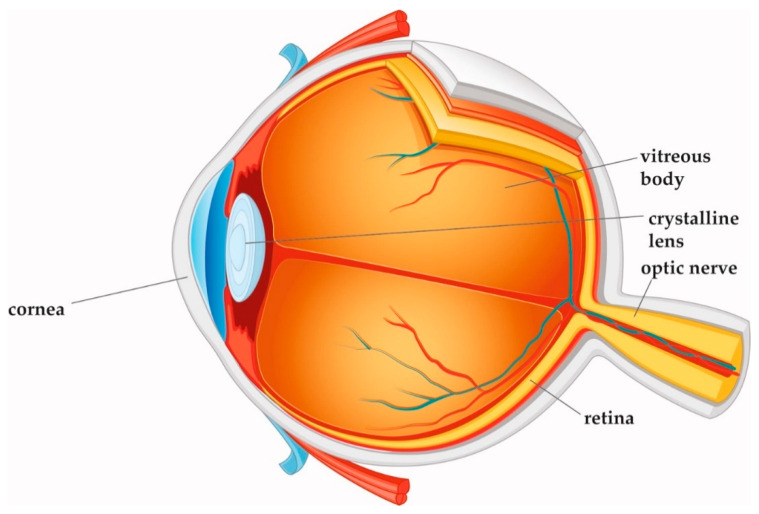
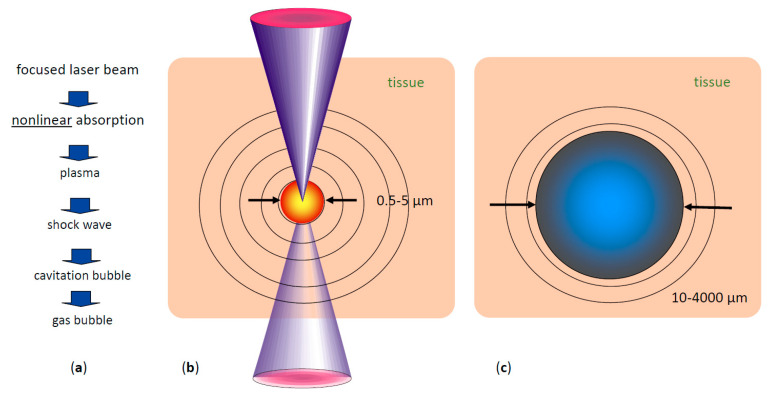
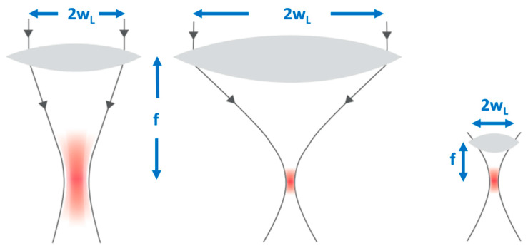
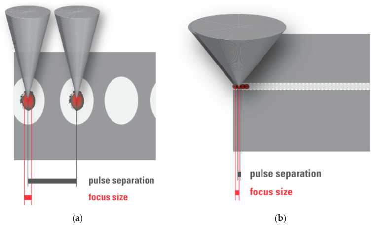
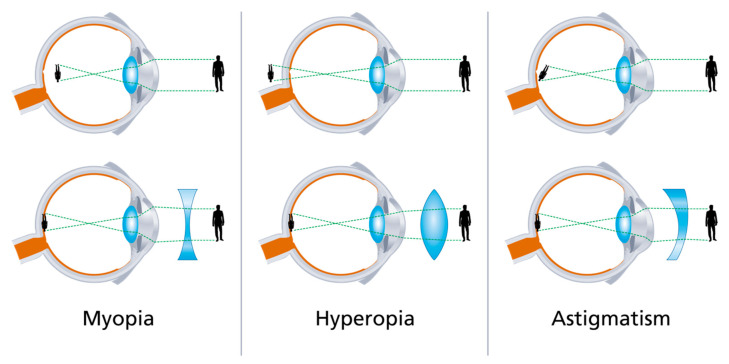
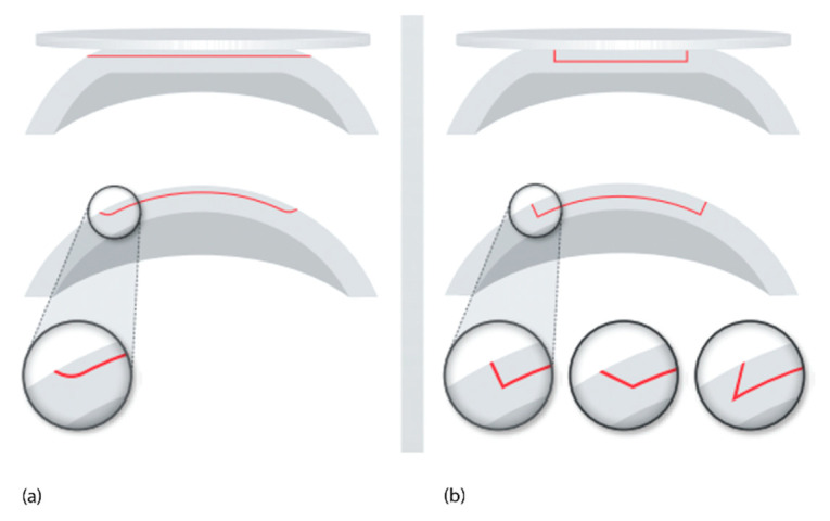
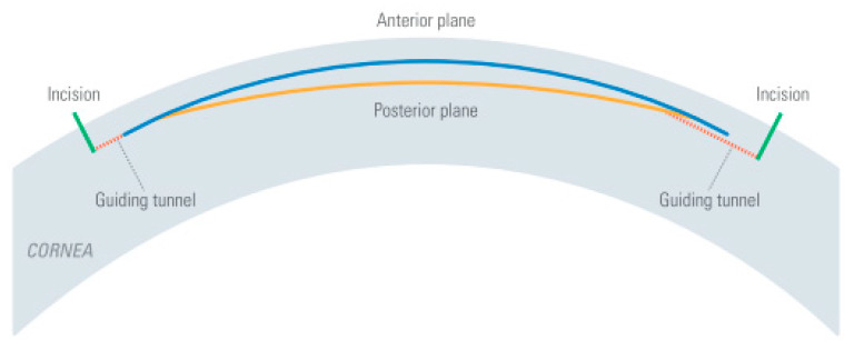
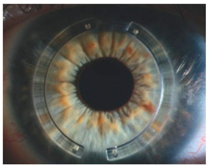
This article provides an overview of both established and innovative applications of femtosecond (fs)-laser-assisted surgical techniques in ophthalmology. Fs-laser technology is unique because it allows cutting tissue at very high precision inside the eye. Fs lasers are mainly used for surgery of the human cornea and lens. New areas of application in ophthalmology are on the horizon. The latest improvement is the high pulse frequency, low-energy concept; by enlarging the numerical aperture of the focusing optics, the pulse energy threshold for optical breakdown decreases, and cutting with practically no side effects is enabled.

Keywords: femtosecond laser; fs-assisted cataract surgery; high pulse frequency; laser-assisted ophthalmic surgery; low energy.


Conflict of interest statement

A.M. is a consultant to Ziemer Ophthalmics, CH-2562 Port, Switzerland.

Figures

Figure 1
Figure 1
Cross-section of the eye. Cornea, crystalline lens, and vitreous body are transparent in the healthy eye.
Figure 2
Figure 2
Short pulse laser effects in tissue: (a) sequence of effects and induced events, (b) plasma size range and pressure wave pattern, (c) range of possible cavitation bubble dimensions (pulse energy-dependent) [9].
Figure 3
Figure 3
The focal volume of a Gaussian laser beam scales with the numerical aperture NA = w/f of the focusing lens. The larger the NA, the smaller the focal spot volume.
Figure 4
Figure 4
(a) High pulse energy, low repetition rate (large spot separation); (b) low pulse energy, high repetition rate (small spot separation, overlapping plasma effects of spots).
Figure 5
Figure 5
Three-dimensional laser focus scan pattern used for the fragmentation of cataractous lenses.
Figure 6
Figure 6
Example of the optical coherence tomography (OCT)-guided placement of an fs-laser cut pattern (blue: corneal anterior and posterior surface; pink and purple: lens anterior and posterior surface; green: iris plane).
Figure 7
Figure 7
Typical eye docking methods of fs lasers: (a) head under fixed laser housing, (b) articulated arm with handpiece placed onto the eye; green: distance of eye surface to laser optics.
Figure 8
Figure 8
Typical patient interface designs: (a) contact interface in direct touch with the cornea (flat or curved), and (b) liquid optics interface, no direct touch on the cornea, no deformation.
Figure 9
Figure 9
Illustration of different types of refractive error and their correction with lenses. Corneal refractive surgery changes the shape of the cornea according to the corrective lenses.
Figure 10
Figure 10
Corneal flaps cut by fs laser: (a) straight plane (red) with continuously curved sides cut during vacuum docking to a flat interface, (b) angulated side cut options (3D cutting geometry).
Figure 11
Figure 11
Schematic view of intrastromal lenticule cuts performed by an fs laser. The lenticule created between the anterior (blue) and posterior (yellow line) cut planes is extracted by the surgeon via an incision (green line). Optionally there is a second incision created to help mobilize the lenticule.
Figure 12
Figure 12
Intrastromal corneal ring segments implanted into fs-laser cut pockets.
Figure 13
Figure 13
Comparison of donor and recipient trephination profiles: (a) applanation, (b) liquid optic interface.
Figure 14
Figure 14
Sidecut profiles: (a) mushroom, (b) top hat, (c) zig-zag.
Figure 15
Figure 15
Illustration of corneal layers.
Figure 16
Figure 16
Deep anterior lamellar keratoplasty (DALK) procedure: (a) OCT-guided placement of the cuts: side cut in green, pre-Descemet’s stroma cut in orange, guiding channel in pink. The posterior cornea is folded due to the applanating docking. (b) Insertion of the cannula for air injection through the precut guiding channel, just above the Descemet’s membrane.

References

    1. Welch A.J., van Gemert M. Optical-Thermal Response of Laser-Irradiated Tissue. Springer; Berlin/Heidelberg, Germany: 2011.
    1. Kaschke M., Donnerhacke K.-H., Rill M.S. Optical Devices in Ophthalmology and Optometry: Technology, Design Principles and Clinical Applications. WILEY-VCH Verlag GmbH & Co. KGaA; Weinheim, Germany: 2014.
    1. Aron-Rosa D., Aron J.J., Griesemann M., Thyzel R. Use of the neodymium-yag laser to open the posterior capsule after lens implant surgery: A preliminary report. Am. Intra-Ocular Implant. Soc. J. 1980;6:352–354. doi: 10.1016/S0146-2776(80)80036-X. - DOI - PubMed
    1. Stern D., Schoenlein R.W., Puliafito C.A., Dobi E.T., Birngruber R., Fujimoto J.G. Corneal Ablation by Nanosecond, Picosecond, and Femtosecond Lasers at 532 and 625 nm. Arch. Ophthalmol. 1989;107:587–592. doi: 10.1001/archopht.1989.01070010601038. - DOI - PubMed
    1. Huang D., Swanson E.A., Lin C.P., Schuman J.S., Stinson W.G., Chang W., Hee M.R., Flotte T., Gregory K., Puliafito C.A., et al. Optical Coherence Tomography. Science. 1991;254:1178–1181. doi: 10.1126/science.1957169. - DOI - PMC - PubMed

LinkOut - more resources