. 2018 Jun 19:5:67.
doi: 10.3389/frobt.2018.00067. eCollection 2018.

Oncilla Robot: A Versatile Open-Source Quadruped Research Robot With Compliant Pantograph Legs

Affiliations

Oncilla Robot: A Versatile Open-Source Quadruped Research Robot With Compliant Pantograph Legs

Alexander T Spröwitz et al. Front Robot AI. .

Abstract

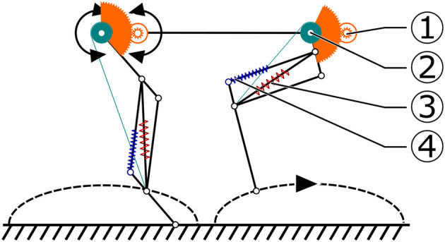
We present Oncilla robot, a novel mobile, quadruped legged locomotion machine. This large-cat sized, 5.1 kg robot is one of a kind of a recent, bioinspired legged robot class designed with the capability of model-free locomotion control. Animal legged locomotion in rough terrain is clearly shaped by sensor feedback systems. Results with Oncilla robot show that agile and versatile locomotion is possible without sensory signals to some extend, and tracking becomes robust when feedback control is added (Ajallooeian, 2015). By incorporating mechanical and control blueprints inspired from animals, and by observing the resulting robot locomotion characteristics, we aim to understand the contribution of individual components. Legged robots have a wide mechanical and control design parameter space, and a unique potential as research tools to investigate principles of biomechanics and legged locomotion control. But the hardware and controller design can be a steep initial hurdle for academic research. To facilitate the easy start and development of legged robots, Oncilla-robot's blueprints are available through open-source. The robot's locomotion capabilities are shown in several scenarios. Specifically, its spring-loaded pantographic leg design compensates for overdetermined body and leg postures, i.e., during turning maneuvers, locomotion outdoors, or while going up and down slopes. The robot's active degree of freedom allow tight and swift direction changes, and turns on the spot. Presented hardware experiments are conducted in an open-loop manner, with little control and computational effort. For more versatile locomotion control, Oncilla-robot can sense leg joint rotations, and leg-trunk forces. Additional sensors can be included for feedback control with an open communication protocol interface. The robot's customized actuators are designed for robust actuation, and efficient locomotion. It trots with a cost of transport of 3.2 J/(Nm), at a speed of 0.63 m s-1 (Froude number 0.25). The robot trots inclined slopes up to 10°, at 0.25 m s-1. The multi-body Webots model of Oncilla robot, and Oncilla robot's extensive software architecture enables users to design and test scenarios in simulation. Controllers can directly be transferred to the real robot. Oncilla robot's blueprints are open-source published (hardware GLP v3, software LGPL v3).

Keywords: multiple gaits; open-loop; open-source; pantograph; pattern generator; quadruped; robot; turning.


Figures

Figure 1
Figure 1
Oncilla quadruped robot: (A) Photo in isometric view (B) exploded view with actuators (colorized) and mechanical components. The brushless leg angle (LA) motors, are placed parallel and off the hip axis (1), the brushless leg length (LL) motors are aligned coaxially with the hip axis (2). A four bar mechanism (3) adducts and abducts (AA joint) the leg, and is actuated by a RC servo motor (4). The parallel leg spring (5) allows the pantograph leg to rotate its distal leg joint under load, the leg's diagonal spring (6) acts as the gravity compensating spring. Robot trunk is (7). (8) shows the vertical force sensor of the robot, (9) indicates the incremental encoder, mounted at the rear end of each brushless motor. LA motor actuates the leg through a spur gear pairing, gear ratio 84:1 (10), LL motor is geared down with a custom planetary gearbox, gear ratio 56:1 (11). (12) shows the hind leg, and (13) the front leg, each pointer indicating the leg's l2 segment.
Figure 2
Figure 2
Oncilla robot: (A) frontal, (B) side view of a computer aided design, with measures for the robot's hip height during standing, its overall height, width and length, and its lateral and fore-aft distance between hip and shoulder joints.
Figure 3
Figure 3
Schematic presentation of Oncilla robot's foot locus movement, created for the simplified-load dynamic-motor (SLDM) model scenario. The SLDM model was applied in the robot's pre-design phase, to estimate required motor and gearbox characteristics. This foot-locus profile was used to calculate leg length (LL, 2) and (LA, 1) loads, for trot gait. The diagonal, gravity compensating leg spring (red, 3) is compressed by flexing the leg through a cable mechanism. Load dependent displacement of the parallel spring (4) during stance phase was ignored in the SLDM model.
Figure 4
Figure 4
Schematics of Oncilla robot's electronics and communication network. Thick lines depict power supply for brushless motors (solid red), servo motors (red dotted), and logic (blue). Thin lines correspond to communication buses. All four legs feature: two brushless motors (M1, M2), one servo motor (S0), three absolute magnetic encoders (ME1, ME2, ME3), three strain sensor conversion channels (Fi, two are used).
Figure 5
Figure 5
Schematic presentation of the three-layered Oncilla application programming interface (API). API levels 0–1 for local access, API level 2 for extended language and tool support over the network.
Figure 6
Figure 6
Hardware experiment. Oncilla robot's center of mass (COM) position and velocity are plotted over time, at locomotion cycle frequency of 3.5 Hz. Shown are instantaneous COM position (red dashed) and velocity (black full). Components are sorted by their left-right, fore-aft, and up-down components. In this example, the robot trotted with an average speed of 0.55 m s-1 and a maximum instantaneous (peak) forward speed of 0.78 m s-1. Vertical displacement of the robot's COM was ±5 mm, average hip height 0.16 m. Average roll angle around fore-aft axis was ±0.02 rad. The average pitch angle around left-right axis was 0.06 ±0.04 rad.
Figure 7
Figure 7
Hardware experiment and results from simplified-load dynamical motor (SLDM) model. Plots show the cost of transport (COT) of the real Oncilla robot and the SLDM model over different speeds. The full power consumption minus the stand-by robot power consumption (19.6 W) was used for the COT calculation. Red diamond (SLDM model) marks show the estimated COT values calculated prior to the construction of Oncilla robot based on a simplified, dynamically articulated robot model. Dark blue data points show the COT-speed values for the real Oncilla robot during level trotting in forward (FW) direction. Round marks indicate the hardware robot's COT during backwards (BW) level trotting. The FW locomotion shows a higher COT up to a speed of 0.4 m s-1, compared to the BW locomotion. The SLDM model continuously underestimates the real robot's COT, but provides a good estimate of the asymptotic decline of COT over speed. The best recorded COT with the real Oncilla robot is 3.2 J/(Nm) at 0.63 m s-1, during FW trotting.
Figure 8
Figure 8
Hardware experiment: snapshots of Oncilla robot descending a slope in forward direction. Further tests were performed with the robot going up the slope, and by letting the robot climbing and descending during backwards locomotion. At steeper slopes, Oncilla robot showed excessive slippage when climbing the slope head on (Table 2). Generally, the robot performed better when locomoting backwards. Snapshots here are flipped horizontally, for reading convenience.
Figure 9
Figure 9
Oncilla robot's force sensor signals for (A) the hardware robot, and (B) its simulated Webots model. Forces are given in multiples of body weight (BW). Recorded are hind right (HR) and left front (LF) legs. Vertical forces Fver,LF: dark blue line, Fver,HR: light blue line. Horizontal forces Fhor,LF: orange line, Fhor,HR: red line. The hardware robot gait is a 2.5 Hz trot, the simulated robot trotted at 3.5 Hz. Hardware data was post-processed by an offset correction, and a 18 Hz low pass filter. The hardware experiment indicates vertical forces around 0.5 BW. Time-wise integration of horizontal forces over stance phase would be zero at constant velocity trotting. Hardware recorded force data however shows in-sum negative impulse i.e., the data indicates a decelerating robot, while the actual robot was trotting at quasi continuous speed. We assume that offsets are created by internally deflected mounting brackets, around the horizontal force sensors. Positive and negative components of horizontal forces extracted from Webots are about equal.
Figure 10
Figure 10
Hardware experiment. The difference between knee and ankle joint position (pkneepankle) is plotted, for the front left (blue line) and a hind left (red line) leg. Stance phases of the front leg are shown with a gray background, white background indicates the swing phase. Leg loading information is imperfect, and joint friction leads to delayed and damped joint movements. This overestimates loading contact times, but can be filtered. The here shown data is not filtered.
Figure 11
Figure 11
Snapshots show Oncilla robot simulated in Webots, with the robot's heading to the right. The robot trots with an average speed of 0.98 m s-1, at locomotion frequency 3.5 Hz. The commanded duty factor is 0.49, the observed duty factor is 0.52 and 0.58 for front and hind legs, respectively. The commanded step length was 0.12 m, the observed step length 0.14 m. For this run, the robot accelerated from its still standing position, without controlled transition. The corresponding video shows the acceleration as short trunk pitching (link in Table S1).
Figure 12
Figure 12
Experiment in Webots. Results are plotted same style as hardware results in Figure 6. The simulated robot's center of mass (COM) position and velocity are shown over time, for a cycle frequency of 3.5 Hz. Shown are instantaneous COM position (dashed red) and velocity (full, black line) components sorted by their left-right, fore-aft, and up-down components. The robot reached an average trotting speed of 0.98 m s-1, at peak speeds of 1.12 m s-1. Vertical COM displacement was ±2 mm, at an average hip height of 0.17 m. Average roll angle was ±0.015 rad. The average pitch angle was -0.03 ±0.015 rad.

References

    1. Ajallooeian M. (2015). Pattern Generation for Rough Terrain Locomotion with Quadrupedal Robots: Morphed Oscillators and Sensory Feedback. PhD thesis, STI, Lausanne.
    1. Ajallooeian M., Gay S., Tuleu A., Spröwitz A., Ijspeert A. J. (2013a). Modular control of limit cycle locomotion over unperceived rough terrain, in 2013 IEEE/RSJ International Conference on Intelligent Robots and Systems (IROS) (Tokyo: IEEE; ), 3390–3397.
    1. Ajallooeian M., Pouya S., Spröwitz A., Ijspeert A. J. (2013b). Central pattern generators augmented with virtual model control for quadruped rough terrain locomotion, in 2013 IEEE International Conference on Robotics and Automation (ICRA) (Karlsruhe: IEEE; ), 3321–3328.
    1. Ajallooeian M., van den Kieboom J., Mukovskiy A., Giese M. A., Ijspeert A. J. (2013c). A general family of morphed nonlinear phase oscillators with arbitrary limit cycle shape. Phys. D 263, 41–56. 10.1016/j.physd.2013.07.016 - DOI
    1. Blickhan R. (1989). The spring-mass model for running and hopping. J. Biomech. 22, 1217–1227. 10.1016/0021-9290(89)90224-8 - DOI - PubMed

LinkOut - more resources