

Deployable, Variable Stiffness, Cable Driven Robot for Minimally Invasive Surgery
- PMID: 33501156
- PMCID: PMC7805644
- DOI: 10.3389/frobt.2019.00141
Deployable, Variable Stiffness, Cable Driven Robot for Minimally Invasive Surgery
Abstract
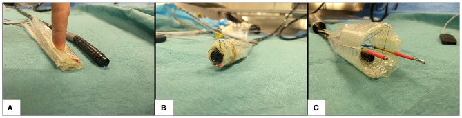
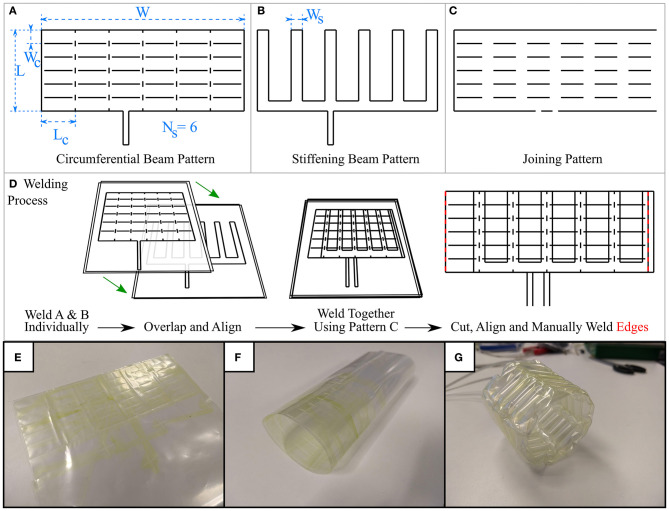
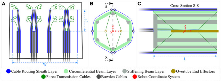
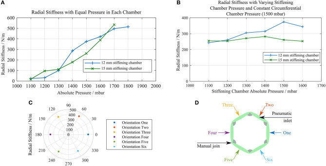
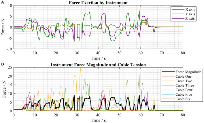
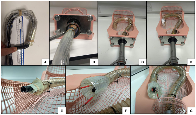
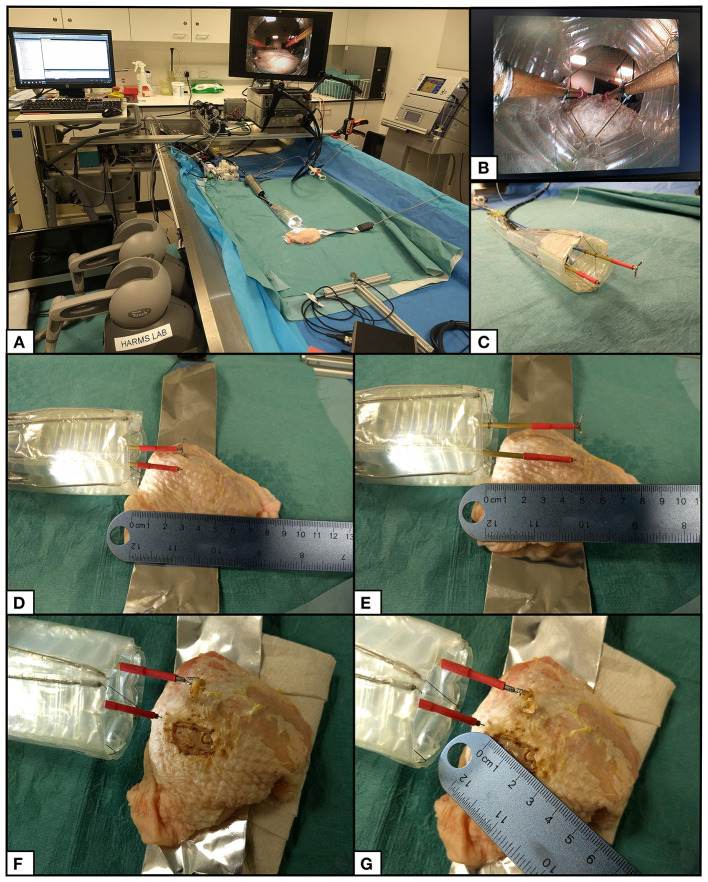
Minimally Invasive Surgery (MIS) imposes a trade-off between non-invasive access and surgical capability. Treatment of early gastric cancers over 20 mm in diameter can be achieved by performing Endoscopic Submucosal Dissection (ESD) with a flexible endoscope; however, this procedure is technically challenging, suffers from extended operation times and requires extensive training. To facilitate the ESD procedure, we have created a deployable cable driven robot that increases the surgical capabilities of the flexible endoscope while attempting to minimize the impact on the access that they offer. Using a low-profile inflatable support structure in the shape of a hollow hexagonal prism, our robot can fold around the flexible endoscope and, when the target site has been reached, achieve a 73.16% increase in volume and increase its radial stiffness. A sheath around the variable stiffness structure delivers a series of force transmission cables that connect to two independent tubular end-effectors through which standard flexible endoscopic instruments can pass and be anchored. Using a simple control scheme based on the length of each cable, the pose of the two instruments can be controlled by haptic controllers in each hand of the user. The forces exerted by a single instrument were measured, and a maximum magnitude of 8.29 N observed along a single axis. The working channels and tip control of the flexible endoscope remain in use in conjunction with our robot and were used during a procedure imitating the demands of ESD was successfully carried out by a novice user. Not only does this robot facilitate difficult surgical techniques, but it can be easily customized and rapidly produced at low cost due to a programmatic design approach.
Keywords: deployable; minimally invasive surgery; rapid manufacture; soft robotics; variable stiffness.
Copyright © 2020 Runciman, Avery, Zhao, Darzi and Mylonas.
Figures
Similar articles
-
Surgical Robot for Intraluminal Access: An Ex Vivo Feasibility Study.Cyborg Bionic Syst. 2020 Dec 5;2020:8378025. doi: 10.34133/2020/8378025. eCollection 2020. Cyborg Bionic Syst. 2020. PMID: 37063410 Free PMC article.
-
A Soft Inflatable Cable-Driven Parallel Robot with A Variable Stiffness End-Effector for Advanced Interventional Endoscopy.IEEE Trans Biomed Eng. 2025 Apr 1;PP. doi: 10.1109/TBME.2025.3552551. Online ahead of print. IEEE Trans Biomed Eng. 2025. PMID: 40168244
-
A cable-driven soft robot surgical system for cardiothoracic endoscopic surgery: preclinical tests in animals.Surg Endosc. 2017 Aug;31(8):3152-3158. doi: 10.1007/s00464-016-5340-9. Epub 2016 Nov 17. Surg Endosc. 2017. PMID: 27858208
-
Flexible endoscopic robot.Minim Invasive Ther Allied Technol. 2015 Feb;24(1):37-44. doi: 10.3109/13645706.2014.996163. Minim Invasive Ther Allied Technol. 2015. PMID: 25627436 Review.
-
Novel endoscopic therapeutics for early gastric cancer.Clin Gastroenterol Hepatol. 2014 Jan;12(1):120-5. doi: 10.1016/j.cgh.2013.07.037. Epub 2013 Aug 15. Clin Gastroenterol Hepatol. 2014. PMID: 23954641 Review.
Cited by
-
Design and evaluation of a pneumatic actuation unit for a wasp-inspired self-propelled needle.PLoS One. 2024 Jul 2;19(7):e0306411. doi: 10.1371/journal.pone.0306411. eCollection 2024. PLoS One. 2024. PMID: 38954720 Free PMC article.
-
A Hybrid Controller for a Soft Pneumatic Manipulator Based on Model Predictive Control and Iterative Learning Control.Sensors (Basel). 2023 Jan 22;23(3):1272. doi: 10.3390/s23031272. Sensors (Basel). 2023. PMID: 36772312 Free PMC article.
-
A Tension Sensor Array for Cable-Driven Surgical Robots.Sensors (Basel). 2024 May 16;24(10):3156. doi: 10.3390/s24103156. Sensors (Basel). 2024. PMID: 38794010 Free PMC article.
-
Development of structured fabric-based endoscopic guiding sheath with tunable diameter and stiffness functions.J Robot Surg. 2025 May 3;19(1):195. doi: 10.1007/s11701-025-02366-6. J Robot Surg. 2025. PMID: 40317344
-
Tissue palpation in endoscopy using EIT and soft actuators.Front Robot AI. 2024 Aug 9;11:1372936. doi: 10.3389/frobt.2024.1372936. eCollection 2024. Front Robot AI. 2024. PMID: 39184867 Free PMC article.
References
-
- Avery J., Runciman M., Darzi A., Mylonas G. P. (2019). Shape sensing of variable stiffness soft robots using electrical impedance tomography. arXiv [Preprint]. 9066–9072. 10.1109/ICRA.2019.8793862 - DOI
-
- Avila-Rencoret F. B., Elson D. S., Mylonas G. (2015). Towards a robotic-assisted cartography of the colon: a proof of concept. Proceedings - IEEE International Conference on Robotics and Automation (Seattle, WA), 1757–1763. 10.1109/ICRA.2015.7139425 - DOI
-
- Avila-Rencoret F. B., Mylonas G. P., Elson D. S. (2018). Robotic wide-field optical biopsy endoscopy, in Biophotonics Congress: Biomedical Optics Congress 2018 (Microscopy/Translational/Brain/OTS) (Hollywood, FL: Optical Society of America; ). 10.1364/TRANSLATIONAL.2018.CF1B.5 - DOI
LinkOut - more resources
Full Text Sources
Miscellaneous